


Understanding Microscopes and Objectives
This is Section 9.1 of the Imaging Resource Guide
Components of Microscopes | Key Concepts and Specifications | Optical Microscopy Application Examples
A microscope is an optical device used to image an object onto the human eye or a video device. The earliest microscopes, consisting of two elements, simply produced a larger image of an object under inspection than what the human eye could observe. The design has evolved over the microscope's history to now incorporate multiple lenses, filters, polarizers, beamsplitters, sensors, illumination sources, and a host of other components. To understand these complex optical devices, consider a microscope's components, key concepts and specifications, and applications.
Components of Microscopes
A compound microscope is one that contains multiple lens elements. It works similar to a simple magnifier which utilizes a single lens to magnify a small object in order for the human eye to discern its details. With a simple magnifier, the object is placed within the focal length of the single lens. This produces a magnified, virtual image. With a microscope, a relay lens system replaces the single lens; an objective and an eyepiece work in tandem to project the image of the object onto the eye, or a sensor – depending upon the application. There are two parts to a microscope that increase the overall system magnification: the objective and the eyepiece. The objective, located closest to the object, relays a real image of the object to the eyepiece. This part of the microscope is needed to produce the base magnification. The eyepiece, located closest to the eye or sensor, projects and magnifies this real image and yields a virtual image of the object. Eyepieces typically produce an additional 10X magnification, but this can vary from 1X – 30X. Figure 1 illustrates the components of a compound microscope. Additionally, Equation 1 demonstrates how to calculate the overall system magnification. In Equation 1, m is magnification.
Figure 1: The components of a compound microscope.
Eyepieces
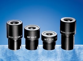
When microscopes were first invented, eyepieces played a major role in their design since they were the only means to actually see the object under inspection. Today, analog or digital cameras are used to project an image of the object onto a monitor or a screen. Microscope eyepieces generally consist of a field lens and an eye lens, though multiple designs exist that each creates a larger field of view (FOV) than a single element design. For a simple guide on selecting the right design, view Choosing the Correct Eyepiece.
Illumination
Illumination within a microscope is just as important as selecting the proper eyepiece or objective. It is crucial to choose the correct illumination in order to obtain the most conclusive results. Before deciding on the type of illumination setup to work with, consider the application setup, object under inspection, and desired results.
Many microscopes utilize backlight illumination compared to traditional direct light illumination because the latter usually over-saturates the object under inspection. A specific type of backlight illumination used in microscopy applications is Koehler illumination. In Koehler illumination, incident light from an illumination source, such as a light bulb, floods the object under inspection with light from behind (Figure 2). It employs two convex lenses: the collector lens and the condenser lens. It is designed to provide bright and even illumination on the object plane and on the image plane where the image produced from the objective is then reimaged through the eyepiece. This is important because it ensures the user is not imaging the filament of the light bulb. Since backlight illumination floods the object with light from behind, it is also referred to as brightfield illumination.
Figure 2: A Koehler illumination setup.
Brightfield illumination requires a change in opacity throughout the object. Without this change, the illumination creates a dark blur around the object. The end result is an image of relative contrast between parts of the object and the light source. In most cases, unless the object is extremely transparent, the resulting image allows the user to see each part of the object with some clarity or resolution. In cases where an object's transparency makes it difficult to distinguish features using brightfield illumination, darkfield illumination can be used.
With darkfield illumination, direct rays of light are not sent into the objective but instead strike the object at an oblique angle. It is important to keep in mind that these rays still illuminate the object in the object plane. The resultant darkfield illumination image produces high-contrast between the transparent object and the light source. When used in a microscopy setup, darkfield illumination produces a light source that forms an inverted cone of light blocking the central rays of light but still allowing the oblique rays to light the object. Figure 3 illustrates a sample darkfield illumination setup where the hollow cone of light is the numerical aperture of the objective. By comparison, no rays are blocked in a brightfield illumination setup. The design of darkfield illumination forces the light to illuminate the object under inspection, but not to enter the optical system, making it better for a transparent object.

Figure 3: A darkfield illumination setup.
A third type of illumination used in microscopy is epi-Illumination. Epi-illumination produces light above the objective. As a result, the objective and epi-illumination source substitute for a Koehler illumination setup. Using the objective for a large section of the illumination makes epi-illumination very compact – a major benefit of this design. Figure 4 illustrates an epi-illumination setup that is used frequently in fluorescence applications. For more information on fluorescence microscopy, view Fluorophores and Optical Filters for Fluorescence Microscopy.
Figure 4: A epi-illumination setup.
Objectives
Objectives allow microscopes to provide magnified, real images and are, perhaps, the most complex component in a microscope system because of their multi-element design. Objectives are available with magnifications ranging from 2X – 200X. They are classified into two main categories: the traditional refractive type and reflective. Each category is further divided into types: finite conjugate and infinite conjugate (infinity corrected). In order to choose the correct objective, it is important to know the benefits of one category and type from another.
Objectives: Refractive
The most commonly used category of objectives is refractive. In a refractive design light passing through the system is refracted, or bent, by the optical elements. Each optical element is typically anti-reflection coated to reduce back reflections and improve overall light throughput. Refractive objectives are often used in machine vision applications that require resolution of extremely fine details. There are multiple refractive objective designs each utilizing different optical configurations. The designs can range from two elements in basic achromatic objectives (an achromatic lens and a meniscus lens) to fifteen elements in plan-apochromatic objectives (Figure 5). Plan-apochromatic objectives are the most complex, high-end objective design with chromatic and flat field correction done within the objective itself.
Figure 5: A apochromatic (left) vs. achromatic (right) objective design.
Objectives: Reflective
Reflective objectives utilize a reflective, or mirror-based design. They are often overlooked in comparison to their refractive counterparts, though they can correct for many issues present in the latter. Reflective objectives consist of a primary and secondary mirror system (Figure 6) to magnify and relay the image of the object under inspection. Edmund Optics® utilizes the popular Schwarzschild design, though other designs are available. Since light is reflected by metallic surfaces and not refracted by glass surfaces, reflective objectives do not suffer from the same aberrations as refractive objectives and, thus, do not need the additional designs to compensate for these aberrations. Reflective objectives can produce higher light efficiency as well as better resolving power for fine detail imaging because the system is primarily dependent upon the mirror coating instead of upon the glass substrate being used. Another benefit of reflective objectives is the possibility of working deeper into either the ultra-violet (UV) or infrared (IR) spectral regions due to the use of mirrors compared to conventional refractive optics.
Figure 6: The anatomy of a reflective objective.
Key Concepts and Specifications
Most microscope objective specifications are listed on the body of the objective itself: the objective design/standard, magnification, numerical aperture, working distance, lens to image distance, and cover slip thickness correction. Figure 7 shows how to read microscope objective specifications. Since the specifications are located directly on the body of the objective, it is easy to know exactly what one has, a very important fact when incorporating multiple objectives into an application. Any remaining specifications, such as focal length, FOV, and design wavelength, can easily be calculated or found in the specifications provided by the vendor or manufacturer.
Figure 7: A typical transmissive microscope objective.
The Objective Standard
If the objective follows a simple microscope standard (such as DIN or JIS) then it is listed on the body to show what required specifications must be present within the system. Most compound microscopes employ the Deutsche Industrie Norm, or DIN, standard. The DIN standard has a 160mm distance from the objective flange to the eyepiece flange (Figure 8). The other available standard is the Japanese Industrial Standard, or JIS. The JIS standard has a 170mm distance from objective flange to eyepiece flange (Figure 9). Paying attention to these two distances is necessary when choosing the proper objective and eyepiece in order to make sure that the image projected from the former is properly imaged through the latter. Though the image distances are different for DIN and JIS, there is no difference in optical performance; they are equal in quality. Similarly, each standard utilizes the same RMS mounting thread of 0.7965" x 36TPI.
DIN and JIS have historically been used when considering a classic compound microscope. Some microscope manufacturers prefer to list the tube lens length by the optical properties instead of the mechanical. For a DIN standard objective, this changes the tube lens length to 150mm because the eyepiece is imaging the intermediate image plane (Figure 8). Lastly, there is a dimension typically listed for objectives to allow the user to consistently know what length it is: the parfocal distance (PD). The parfocal distance is the distance from the flange of the objective to the object under inspection. For DIN objectives this distance is a standard 45mm and for JIS is it 36mm (Figures 8 and 9).
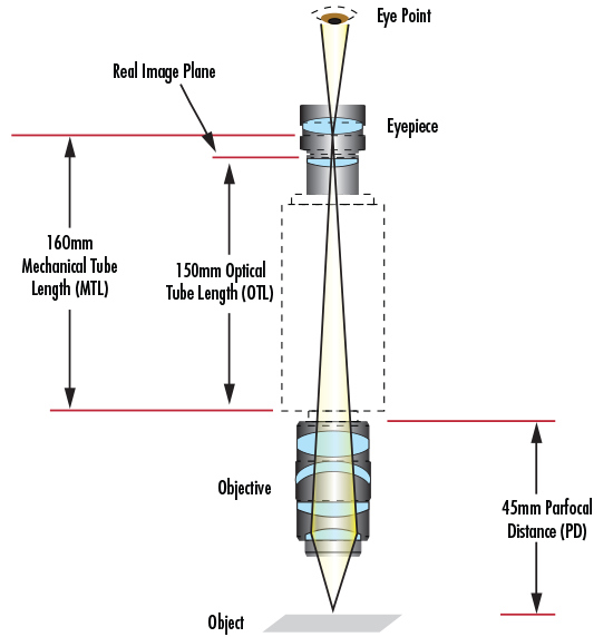
Figure 8: The DIN standard.
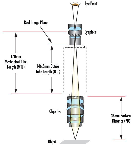
Figure 9: The JIS standard.
Magnification
Eyepieces and objectives both have magnification that each contribute to the overall system magnification. Magnification is usually denoted by an X next to a numeric value. Most objectives contain a colored band around the entire circumference of the body that indicates their magnification (Figure 7). For example, a yellow band denotes a 10X magnification.
Numerical Aperture
The Numerical Aperture (NA) of an objective is a function of the focal length and the entrance pupil diameter. Large NA objectives sometimes require the use of immersion oils between the object under inspection and the front of the objective. This is because the highest NA that can be achieved within air is an NA of 1 (corresponding to 90° angle of light). To get a larger angle and increase the amount of light entering the objective (Equation 2), it is necessary to use immersion oil (index of refraction typically = 1.5) to change the refractive index between the object and the objective. High NA objectives in conjunction with immersion oil are a simple alternative to changing objectives, a move that may be costly.
Field of View
Field of view or FOV is the area of the object that is imaged by a microscope system. The size of the FOV is determined by the objective magnification. When using an eyepiece-objective system, the FOV from the objective is magnified by the eyepiece for viewing. In a camera-objective system, that FOV is relayed onto a camera sensor. The sensor on a camera is rectangular and therefore can only image a portion of the full circular FOV from the objective. In contrast, the retina in your eye can image a circular area and captures the full FOV. This is why the FOV produced by a camera-microscope system is typically slightly smaller than that of an eyepiece-microscope system. Equations 3 and 4 can be used to calculate the FOV in the aforementioned systems. In Equations 3 and 4, $ \small{H_{\small{\text{Camera Sensor}}}} $ is the sensor size of the camera and $ \small{H_{\small{\text{Eyepiece Field Stop}}}} $ is the field stop of the eyepiece.
Cover Slip Thickness
When viewing fluid materials such as bacteria, cell cultures, blood, etc, it is necessary to use a coverslip in order to protect the object under inspection and microscope components from contamination. A coverslip, or glass microscope slide, changes the way light refracts from the object into the objective. As a result, the objective needs to make proper optical corrections to produce the best quality image. This is why objectives denote a range of coverslip thicknesses for which they are optimized. Typically, this is listed after the infinity symbol (which denotes that an objective is an infinite conjugate, or infinity corrected design) and ranges from zero (no coverslip correction) to 0.17mm.
Quality Correction
The quality of an objective and eyepiece determine how well the system performs. In addition to choosing the magnification and complexity of the design, understanding correct quality correction is extremely important when deciding on the type of objective to use. Quality correction (i.e. achromatic, apochromatic, plan, semi-plan) is denoted on the objective itself to allow the user to easily see the design of the objective in question. There are typically two levels of chromatic aberration correction: achromatic and apochromatic. Achromatic objectives are among the simplest and least expensive of objectives. They are designed to correct for chromatic aberration in the red and blue wavelengths, in addition to being corrected for spherical aberration in a green wavelength. Limited correction for chromatic aberration and lack of a flat FOV reduce objective performance. Apochromatic objectives, by contrast, provide higher precision and are chromatically corrected for red, blue, and yellow. They also provide spherical aberration correction for a broad spectral range and generally have a long working distance given the extremely high numerical apertures (NA) that this optical design offers. Apochromatic objectives are ideal for white light applications, whereas achromatic objectives are best suited for monochromatic. Both objective designs, however, suffer significantly from distortion and field curvature, which worsen as objective magnification increases. Therefore, it is always important to focus on the complete system performance, rather than just objective performance alone.
Plan, also known as planar, semi-plan, semi-planar, or microplan, objectives correct for field curvature. Field curvature is a type of aberration present when the off-axis image cannot be brought to focus in a flat image plane, resulting in a blurred image as it deviates from the optical axis. Figure 10 illustrates field flatness measured radially from the center in achromatic, semi-plan, and plan objective designs. Achromatic objectives have a flat field in the center 65% of the image. Plan objectives correct best overall and display better than 90% of the field flat and in focus. Semi-plan objectives are intermediate to the other two types with 80% of the field appearing flat.

Figure 10: Flat field correction: achromatic 65% (left) vs. semiplan 80% (center) vs. plan 90% (right).
Fluorite objectives further correct for aberrations using advanced glass types containing fluorspar or other synthetic substitutes. Just like achromatic objectives, fluorite objectives are designed to correct for chromatic aberrations for red and blue wavelengths. However, fluorite objectives are designed to correct for spherical aberration at two or three wavelengths instead of just green, typically have a higher NA, and feature a better resolving power and higher degree of contrast.
Finite Conjugate
In a finite conjugate optical design, light from a source (not at infinity) is focused down to a spot (Figure 11). In the case of a microscope, the image of the object under inspection is magnified and projected onto the eyepiece, or sensor if using a camera. The particular distance through the system is characterized by either the DIN or JIS standard; all finite conjugate microscopes are either one of these two standards. These types of objectives account for the majority of basic microscopes. Finite conjugate designs are used in applications where cost and ease of design are major concerns.
Figure 11: A simplified finite conjugate microscope design.
Infinite Conjugate (Infinity Corrected)
In an infinite conjugate, or infinity corrected, optical design, light from a source placed at infinity is focused down to a small spot. In an objective, the spot is the object under inspection and infinity points toward the eyepiece, or sensor if using a camera (Figure 12). This type of modern design utilizes an additional tube lens between the object and eyepiece in order to produce an image. Though this design is much more complicated than its finite conjugate counterpart, it allows for the introduction of optical components such as filters, polarizers, and beamsplitters into the optical path. As a result, additional image analysis and extrapolation can be performed in complex systems. For example, adding a filter between the objective and the tube lens allows one to view specific wavelengths of light or to block unwanted wavelengths that would otherwise interfere with the setup. Fluorescence microscopy applications utilize this type of design. Another benefit of using an infinite conjugate design is the ability to vary magnification according to specific application needs. Since the objective magnification is the ratio of the tube lens focal length $ ( \small{f_{\small{\text{Tube Lens}}}} ) $ to the objective focal length $ (\small{f_{\small{\text{Objective}}}} ) $ (Equation 5), increasing or decreasing the tube lens focal length changes the objective magnification. Typically, the tube lens is an achromatic lens with a focal length of 200mm, but other focal lengths can be substituted as well, thereby customizing a microscope system's total magnification. If an objective is infinite conjugate, there will be an infinity symbol located on the body of the objective.

Figure 12: A simplified infinite conjugate (infinity corrected) microscope design.
Optical Microscopy Application Examples
In order to understand how the components of a microscope can be integrated with various optical, imaging, and photonics products, consider the following optical microscopy applications: fluorescence microscopy and laser ablation. Each utilizes its own unique setup in order to work with components from a microscope.
Fluorescence Microscopy
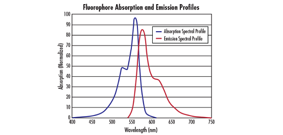
A fluorophore (or fluorescent dye) is used to mark proteins, tissues, and cells for examination or study. Fluorophores can absorb light of one wavelength and emit (fluoresce) light of another wavelength. In a typical fluorescence microscopy setup three filters are used: an excitation filter, an emission filter and a dichroic filter. Each fluorophore has a specific absorption or excitation wavelength band, the excitation filter will transmit only that specific range of wavelengths. The fluorophore, once excited, will emit a different range of wavelengths. The emission filter transmits only the emission wavelengths. A dichroic filter that is specifically designed to reflect the emission wavelengths and transmit the excitation wavelengths is used to separate the excitation and emission channels. Figure 13 illustrates a typical fluorescence imaging setup. For additional information on fluorescence microscopy, view Fluorophores and Optical Filters for Fluorescence Microscopy.
Figure 13: A typical fluorescence microscope setup.
Laser Ablation
Two common uses of lasers are to (1) heat material onto a base or (2) to ablate material off of a base. Laser ablation systems require microscope components because of the precision beam manipulation (i.e. focusing, bending, scattering reduction, etc) required. A laser ablation setup typically contains custom optics, rather than off-the-shelf components, with the laser precisely designed into the system (Figure 14). The laser is oriented in an epi-illumination design to utilize the microscope objective's ability to focus light at the object plane, and to produce extremely small spot sizes with minimal aberrations. Also, an eyepiece allows the user to see where the laser is located and to make sure everything is working properly. Filters are necessary to block the laser from causing damage to the user's eye. Laser ablation setups are used in medical and biological applications because they offer higher precision than conventional surgical methods.
Figure 14: A typical laser ablation setup.
Microscope and objectives are complex optical systems with many uses. They are no longer used solely for biological setups (e.g. looking at cheek cells in an introductory biology class); rather, they can be used to study the emission wavelength of a flourophore, to analyze a 5μm defect on a machined part, to oversee the ablation of material off a base, and within a host of other applications in the optics, imaging, and photonics industries. Understanding the importance of each constituent part of a microscope and their specifications enables any user to choose the best system and achieve the best results.
tend to be on the order of a pixel or less.


or view regional numbers
QUOTE TOOL
enter stock numbers to begin
Copyright 2023 | Edmund Optics, Ltd Unit 1, Opus Avenue, Nether Poppleton, York, YO26 6BL, UK
California Consumer Privacy Acts (CCPA): Do Not Sell or Share My Personal Information
California Transparency in Supply Chains Act
This content may include material that has been generated or modified using artificial intelligence (AI).
The FUTURE Depends On Optics®