


Common Illumination Types
This is Section 11.1 of the Imaging Resource Guide
Often, a customer struggles with contrast and resolution problems in an imaging system, while underestimating the power of proper illumination. In fact, desired image quality can typically be met by improving a system's illumination rather than investing in higher resolution detectors, imaging lenses, and software. System integrators should remember that proper light intensity in the final image is directly dependent upon component selection.
Correct illumination is critical to an image system and improper illumination can cause a variety of image problems. Blooming or hot spots, for example, can hide important image information, as can shadowing. In addition, shadowing can also cause false edge calculations when measuring, resulting in inaccurate measurements. Poor illumination can also result in a low signal-to-noise ratio. Non-uniform lighting, in particular, can harm signal-to-noise ratios and make tasks such as thresholding more difficult. These are only a few of the reasons why correct illumination for your application is so important.
The pitfalls of improper illumination are clear, but how are they avoided? To ensure optimal illumination when integrating a system, it is important to recognize the role that choosing the right components plays. Every component affects the amount of light incident on the sensor and, therefore, the system's image quality. The imaging lens' aperture (f/#) impacts the amount of light incident on the camera. Illumination should be increased as the lens aperture is closed (i.e. higher f/#). High power lenses usually require more illumination, as smaller areas viewed reflect less light back into the lens. The camera's minimum sensitivity is also important in determining the minimum amount of light required in the system. In addition, camera settings such as gain, shutter speed, etc., affect the sensor's sensitivity. Fiber optic illumination usually involves an illuminator and light guide, each of which should be integrated to optimize lighting at the object.
| Table 1: Key Photometric Units | |
|---|---|
| 1 footcandle | = 1 lumen/ft2 |
| 1 footcandle | = 10.764 meter candles |
| 1 footcandle | = 10.764 lux |
| 1 candle | = 1 lumen/steradian |
| 1 candle | = 3.142 x 10⁻⁴ Lambert |
| 1 Lambert | = 2.054 candle/in2 |
| 1 lux | = meter candle |
| 1 lux | = 0.0929 footcandle |
| 1 meter candle | = 1 lumen/m2 |
The light intensity for our illumination products is typically specified in terms of footcandles (English unit). Lux, the SI unit equivalent, can be related to footcandles as follows: 1 lux = 0.0929 footcandle.
| Table 2: Illumination Comparison | ||
|---|---|---|
| Application Requirement | Object Under Inspection | Suggested Type of Illumination |
| Reduction of specularity | Shiny object | Diffuse front, diffuse axial, polarizing |
| Even illumination of object | Any type of object | Diffuse front, diffuse axial, ring light |
| Highlight surface defects or topology | Nearly flat (2-D) object | Single directional, structured light |
| Highlight texture of object with shadows | Any type of object | Directional, structured light |
| Reduce shadows | Object with protrusions, 3-D object | Diffuse front, diffuse axial, ring light |
| Highlight defects within object | Transparent object | Darkfield |
| Silhouetting object | Any type of object | Backlighting |
| 3-D shape profiling of object | Object with protrusions, 3-D object | Structured light |
Types of Illumination
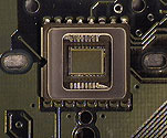
Since proper illumination is often the determining factor between a system's success and failure, many specific products and techniques have been developed to overcome the most common lighting obstacles. The target used throughout this section was developed to demonstrate the strengths and weaknesses of these various lighting schemes for a variety of object features. The grooves, colors, surface deformations, and specular areas on the target represent some of the common trouble areas that may demand special attention in actual applications.
| Directional Illumination – Point source illumination from single or multiple sources. Lenses can be used to focus or spread out illumination. | |
| Pros | Bright, flexible, and can be used in various applications. Easily fit into different packaging. |
| Cons | Shadowing and glare. |
| Useful Products | Fiber optic light guides, focusing assemblies, LED spot lights, and incandescent light. |
| Application | Inspection and measurement of matte and flat objects. |
| Glancing Illumination – Point source illumination similar to directional illumination, except at a sharp angle of incidence. | |
| Pros | Shows surface structure and enhances object topography. |
| Cons | Hot spots and extreme shadowing. |
| Useful Products | Fiber optic light guides, focusing assemblies, LED spot lights, and incandescent light and line light guides. |
| Application | Identifying defects in an object with depth and examining finish of opaque objects. |
| Diffuse Illumination – Diffuse, even light from an extended source. | |
| Pros | Reduces glare and provides even illumination. |
| Cons | Large and difficult to fit in confined spaces. |
| Useful Products | Fluorescent linear lights. |
| Application | Best for imaging large, shiny objects with large working distances. |
| Ring Light – Coaxial illumination that mounts directly on a lens. | |
| Pros | Mounts directly to lens and reduces shadowing. Uniform illumination when used at proper distances. |
| Cons | Circular glare pattern from reflective surfaces. Works only in relatively short working distances. |
| Useful Products | Fiber optic ring light guides and fluorescent ring lights; LED ring lights. |
| Application | Wide variety of inspection and measurement systems with matte objects. |
| Diffuse Axial Illumination – Diffuse light in-line with the optics. Lens looks through a beamsplitter that is reflecting light onto the object. Illumination is coaxial to imaging access. | |
| Pros | Very even and diffuse; greatly reduces shadowing; very little glare. |
| Cons | Large and difficult to mount; limited working distance; low throughput such that multiple fiber optic sources may be needed to provide sufficient illumination. |
| Useful Products | Fiber optic diffuse axial attachment. Single or multiple fiber optic illuminators. Single, dual, or quad fiber bundles depending on size of attachment and number of illuminators used. LED diffuse axial illuminator. |
| Application | Measurements and inspection of shiny objects. |
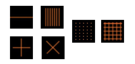
| Structured Light (Line Generators) – Patterns that are projected onto the object. Typically laser projected lines, spots, grids, or circles. | |
| Pros | Enhances surface features by providing intense illumination over a small area. Can be used to get depth information from object. |
| Cons | May cause blooming and is absorbed by some colors. |
| Useful Products | Lasers with line generating or diffractive pattern generating optics. |
| Application | Inspection of three-dimensional objects for missing features. Topography measurements. |
| Polarized Light – A type of directional illumination that makes use of polarized light to remove specularities and hot spots. | |
| Pros | Provides even illumination over the entire surface of the object under polarization. Reduces glare to make surface features discernable. |
| Cons | Overall intensity of light is reduced after polarization filter is placed in front of light source and/or imaging lens. |
| Useful Products | Polarization filters and Polarizer/ Analyzer adapters. |
| Application | Measurements and inspection of shiny objects. |
| Darkfield – Light enters a transparent or translucent object through the edges perpendicular to the lens. | |
| Pros | High contrast of internal and surface details. Enhances scratches, cracks, and bubbles in clear objects. |
| Cons | Poor edge contrast. Not useful for opaque objects. |
| Useful Products | Fiber optic darkfield attachment, line light guides, and laser line generators. |
| Application | Glass and plastic inspection. |
| Brightfield/Backlight – Object is lit from behind. Used to silhouette opaque objects or for imaging through transparent objects. | |
| Pros | High contrast for edge detection. |
| Cons | Eliminates surface detail. |
| Useful Products | Fiber optic backlights and LED backlights. |
| Application | Targets and test patterns, edge detection, measurement of opaque objects and sorting of translucent colored objects. |
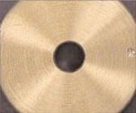
Filtering Provides Various Levels of Contrast
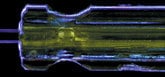
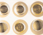
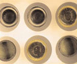
Examples illustrate darkfield and backlight illumination with assorted color filters. Note: Images taken with 10X Close Focus Zoom Lens #54-363: Field of View = 30mm, Working Distance = 200mm.
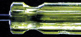
Darkfield Only Defects appear white
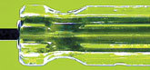
Darkfield with Blue Filter Defects appear blue
Darkfield and Backlight No filter used, but edge contrast improves
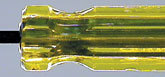
Darkfield without Filter and Backlight with Yellow Filter Enhances overall contrast, defects appear white in contrast to rest of field
Image Enhancement using Polarizers
A polarizer is useful for eliminating specular reflections (glare) and bringing out surface defects in an image. A polarizer can be mounted either on the light source, on the video lens, or on both depending upon the object under inspection. When two polarizers are used, one on the illumination source and one on the video lens, their polarization axes must be oriented perpendicular to each other. The following are polarization solutions to glare problems for several material types and circumstances.
Problem 1
The object is non-metallic and illumination strikes it at a sharp angle.
Solution 1
A polarizer on the lens is usually sufficient for blocking glare. (Rotate the polarizer until glare is at a minimum.) Add a polarizer in front of the light source if glare is still present.
Without Polarizers
Using Polarizers
Problem 2
The object has a metallic or shiny surface.
Solution 2
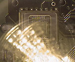
Mounting a polarizer on the light source as well as on the lens is recommended for enhancing contrast and bringing out surface details. The polarized light incident on the shiny surface will remain polarized when it's reflected. Surface defects in the metal will alter the polarization of the reflected light. Turning the polarizer on the lens so its polarization axis is perpendicular to that of the illumination source will reduce the glare and make scratches and digs in the surface visible.
Without Polarizers

Using Polarizers
Problem 3
The object has both highly reflective and diffuse areas.
Solution 3
Using two polarizers with perpendicular orientation will eliminate hot spots in the image caused by the metallic parts. The rest of the field will be evenly illuminated due to the diffuse areas reflecting randomly polarized light to the lens.
Without Polarizers


or view regional numbers
QUOTE TOOL
enter stock numbers to begin
Copyright 2023 | Edmund Optics, Ltd Unit 1, Opus Avenue, Nether Poppleton, York, YO26 6BL, UK
California Consumer Privacy Acts (CCPA): Do Not Sell or Share My Personal Information
California Transparency in Supply Chains Act
This content may include material that has been generated or modified using artificial intelligence (AI).
The FUTURE Depends On Optics®