


Optics 101: Level 1 Theoretical Foundations
The Electromagnetic Spectrum | Interference | Reflection| Refraction | Dispersion | Diffraction
Optics is the branch of physics that deals with light and its properties and behavior. It is a vast science covering many simple and complex subjects ranging from the reflection of light off a metallic surface to create an image, to the interaction of multiple layers of coating to create a high optical density rugate notch filter. As such, it is important to learn the basic theoretical foundations governing the electromagnetic spectrum, interference, reflection, refraction, dispersion, and diffraction before picking the best component for one's optics, imaging, and/or photonics applications.
THE ELECTROMAGNETIC SPECTRUM
Light is a type of electromagnetic radiation usually characterized by the length of the radiation of interest, specified in terms of wavelength, or lambda (λ). Wavelength is commonly measured in nm (10-9 meters) or μm (10-6 meters). The electromagnetic spectrum encompasses all wavelengths of radiation ranging from long wavelengths (radio waves) to very short wavelengths (gamma rays); Figure 1 illustrates this vast spectrum. The most relevant wavelengths to optics are the ultraviolet, visible, and infrared ranges. Ultraviolet (UV) rays, defined as 1– 400nm, are used in tanning beds and are responsible for sunburns. Visible rays, defined as 400 - 750nm, comprise the part of the spectrum that can be perceived by the human eye and make up the colors people see. The visible range is responsible for rainbows and the familiar ROYGBIV - the mnemonic many learn in school to help memorize the wavelengths of visible light starting with the longest wavelength to the shortest. Lastly, infrared (IR) rays, defined as 750nm – 1000μm, are used in heating applications. IR radiation can be broken up further into near-infrared (750nm - 3μm), mid-wave infrared (3 - 30μm) and far-infrared (30 – 1000μm).
Figure 1: Electromagnetic Spectrum
INTERFERENCE
Isaac Newton (1643 - 1727) was one of the first physicists to propose that light was comprised of small particles. A century later, Thomas Young (1773 - 1829) proposed a new theory of light which demonstrated light's wave qualities. In his double-slit experiment, Young passed light through two closely spaced slits and found that the light interfered with itself (Figure 2). This interference could not be explained if light was purely a particle, but could if light was a wave. Though light has both particle and wave characteristics, known as the wave-particle duality, the wave theory of light is important in optics while the particle theory in other branches of physics.
Interference occurs when two or more waves of light add together to form a new pattern. Constructive interference occurs when the troughs of the waves align with each other, while destructive interference occurs when the troughs of one wave align with the peaks of the other (Figure 3). In Figure 3, the peaks are indicated with blue and the troughs with red and yellow. Constructive interference of two waves results in brighter bands of light, whereas destructive interference results in darker bands. In terms of sound waves, constructive interference can make sound louder while destructive interference can cause dead spots where sound cannot be heard.
Interference is an important theoretical foundation in optics. Thinking of light as waves of radiation similar to ripples in water can be extremely useful. In addition, understanding this wave nature of light makes the concepts of reflection, refraction, dispersion and diffraction discussed in the following sections easier to understand.
Figure 2: Thomas Young's Double-Slit Experiment
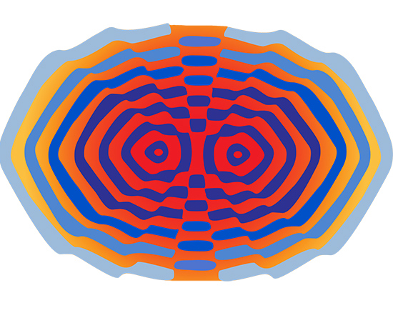
Figure 3: Constructive and Destructive Interference
REFLECTION
Reflection is the change in direction of a wavefront when it hits an object and returns at an angle. The law of reflection states that the angle of incidence (angle at which light approaches the surface) is equal to the angle of reflection (angle at which light leaves the surface). Figure 4 illustrates reflection from a first surface mirror. Ideally, if the reflecting surface is smooth, all of the reflected rays will be parallel, defined as specular, or regular, reflection. If the surface is rough, the rays will not be parallel; this is referred to as diffuse, or irregular, reflection. Mirrors are known for their reflective qualities which are determined by the material used and the coating applied.
Figure 4: Reflection from a First Surface Mirror
REFRACTION
While reflection causes the angle of incidence to equal the angle of reflection, refraction occurs when the wavefront changes direction as it passes through a medium. The degree of refraction is dependent upon the wavelength of light and the index of refraction of the medium. Index of refraction (n) is the ratio of the speed of light in a vacuum (c) to the speed of light within a given medium (v). This can be mathematically expressed by Equation 1. Index of refraction is a means of quantifying the effect of light slowing down as it enters a high index medium from a low index medium (Figure 5).
Figure 5: Light Refraction from a Low Index to a High Index Medium
where n1 is the index of the incident medium, θ1 is the angle of the incident ray, n2 is the index of the refracted/reflected medium, and θ2 is the angle of the refracted/reflected ray.
If the angle of incidence is greater than a critical angle θc (when the angle of refraction = 90°), then light is reflected instead of refracted. This process is referred to as total internal reflection (TIR). Figure 6 illustrates TIR within a given medium.
Figure 6: Total Internal Reflection
TIR is mathematically expressed by Equation 3:
Total Internal Reflection is responsible for the sparkle one sees in diamonds. Due to their high index of refraction, diamonds exhibit a high degree of TIR which causes them to reflect light at a variety of angles, or sparkle. Another notable example of TIR is in fiber optics, where light entering one end of a glass or plastic fiber optic will undergo several reflections throughout the fiber's length until it exits the other end (Figure 7). Since TIR occurs for a critical angle, fiber optics have specific acceptance angles and minimum bend radii which dictate the largest angle at which light can enter and be reflected and the smallest radii the fibers can be bent to achieve TIR.
Figure 7: Total Internal Refraction in a Single Fiber Optic
DISPERSION
Dispersion is a measure of how much the index of refraction of a material changes with respect to wavelength. Dispersion also determines the separation of wavelengths known as chromatic aberration (Figure 8). A glass with high dispersion will separate light more than a glass with low dispersion. One way to quantify dispersion is to express it by Abbe number. Abbe number (vd) is a function of the refractive index of a material at the f
The chromatic aberration caused by dispersion is responsible for the familiar rainbow effect one sees in optical lenses, prisms, and similar optical components. Dispersion can be a highly desirable phenomenon, as in the case of an equilateral prism to split light into its components colors. However, in other applications, dispersion can be detrimental to a system's performance.
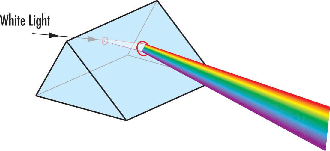
Figure 8: Dispersion through a Prism
DIFFRACTION
The interference patterns created by Thomas Young's double-slit experiment can also be characterized by the phenomenon known as diffraction. Diffraction usually occurs when waves pass through a narrow slit or around a sharp edge. In general, the greater the difference between the size of the wavelength of light and the width of the slit or object the wavelength encounters, the greater the diffraction. The best example of diffraction is demonstrated using diffraction gratings. A diffraction grating's closely spaced, parallel grooves cause incident monochromatic light to bend, or diffract. The degree of diffraction creates specific interference patterns. Figures 9 and 10 illustrate various patterns achieved with diffractive optics. Diffraction is the underlying theoretical foundation behind many applications using diffraction gratings, spectrometers, monochrometers, laser projection heads, and a host of other components.

Multi-Line Red Laser Diffraction Pattern
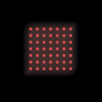
Dot Matrix Red Laser Diffraction Pattern
The basic theoretical foundations governing the electromagnetic spectrum, interference, reflection, refraction, dispersion, and diffraction are important stepping stones to more complex optical concepts. Light's wave properties explain a great deal of optics; understanding the fundamental concepts of optics can greatly increase one's understanding of the way light interacts with a variety of optical, imaging, and photonics components.
References
- Greivenkamp, John E. Field Guide to Geometrical Optics. Vol. FG01. Bellingham, WA: SPIE—The International Society for Optical Engineers, 2004.
- Wilson, Jerry D., Anthony J. Buffa, and Bo Lou. College Physics. 7th ed. Boston, MA: Addison-Wesley, 2009.
- Young, Hugh D., and Roger A. Freedman. University Physics. 9th ed. Reading, MA: Addison-Wesley, 1996.
or view regional numbers
QUOTE TOOL
enter stock numbers to begin
Copyright 2023 | Edmund Optics, Ltd Unit 1, Opus Avenue, Nether Poppleton, York, YO26 6BL, UK
California Consumer Privacy Acts (CCPA): Do Not Sell or Share My Personal Information
California Transparency in Supply Chains Act
This content may include material that has been generated or modified using artificial intelligence (AI).
The FUTURE Depends On Optics®