Understanding Ball Lenses
Ball lenses are great optical components for improving signal coupling between fibers, emitters, and detectors. They are also used in endoscopy, bar code scanning, ball pre-forms for aspheric lenses, and sensor applications. Ball lenses are manufactured from a single substrate of glass and can focus or collimate light, depending upon the geometry of the input source. Half-ball lenses are also common and can be interchanged with full ball lenses if the physical constraints of an application require a more compact design.
Essential Equations for Using Ball Lenses
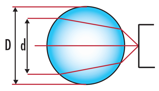
There are five key parameters needed to understand and use ball lenses (Figure 1): Diameter of Input Source $ \small{\left( d \right)} $, Diameter of Ball Lens $ \small{\left( D \right)} $, Effective Focal Length of Ball Lens $ \small{\left( \text{EFL} \right)} $, Back Focal Length of Ball Lens $ \small{\left( \text{BFL} \right)} $ and Index of Refraction of Ball Lens $ \small{\left( n \right)} $.

Figure 1: Key Parameters
$ \small{\text{EFL}} $ is very simple to calculate (Equation 1) since there are only two variables involved: Diameter of Ball Lens $ \small{\left( D \right)} $ and Index of Refraction $ \small{\left( n \right)} $. $ \small{\text{EFL}} $ is measured from the center of the ball lens, as indicated in Figure 1. $ \small{\text{BFL}} $ (Equation 2) is easily calculated once $ \small{\text{EFL}} $ and $ \small{D} $ are known.
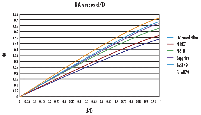
For collimated incident light, the numerical aperture $ \small{\left( \text{NA} \right)} $ of the ball lens is dependent on the size of the ball lens $ \small{\left( D \right)} $, its index of refraction $ \small{\left( n \right)} $, and the diameter of the input source $ \small{\left( d \right)} $. Using $ \small{f / \#} = \tfrac{\text{EFL}}{d} $, a relation between $ \small{\left( \text{NA} \right)} $ and $ \tfrac{d}{D} $ can be obtained (Equation 3), which is plotted in Figure 2.
Equation 3 assumes that the refractive index outside of the ball lens $ \small{\left( n_m \right)} $ equals 1. In the paraxial limit (i.e. $ \tfrac{d}{D} << 1 $), the numerical aperture can be estimated from the f-number as $ \small{\text{NA} \approx } \tfrac{1}{2 \times f / \#} $, which yields Equation 4.

Figure 2: Numerical Aperture vs. Diameter for Ball Lens Glass Types offered by Edmund Optics®. ($ \small{n} $ at 587.6nm and $ \small{n_m = 1} $)
As $ \tfrac{d}{D} $ increases, the focused spot size at the back focal length of the lens increases, due to increased spherical aberration.
Application Examples
Example 1: Laser to Fiber Coupling
When coupling light from a laser into a fiber optic, the choice of ball lens is dependent on the $ \small{\text{NA}} $ of the fiber and the diameter of the laser beam, or the input source. The diameter of the laser beam is used to determine the $ \small{\text{NA}} $ of the ball lens. The $ \small{\text{NA}} $ of the ball lens must be less than or equal to the $ \small{\text{NA}} $ of the fiber optic in order to couple all of the light. The ball lens is placed at its back focal length from the fiber as shown in Figure 3.

Figure 3: Laser to Fiber Coupling
Initial Parameters
Diameter of Input Laser Beam = 2mm
Index of Refraction of Ball Lens = 1.5168
Numerical Aperture of Fiber Optic = 0.22
From Figure 2, the $ \small{\text{NA}} $ of an N-BK7 ball lens is about 0.22 for $ \tfrac{d}{D} \small{\approx 0.3 \text{ to } 0.35} $. Equation 3 yields $ \tfrac{d}{D} \small{\approx 0.33} $ for $ \small{\text{NA}} = 0.22 $. You would need an N-BK7 ball lens with a diameter greater than 6mm ( $ \approx \frac{2 \text{mm}}{0.33} $) to couple a 2mm laser source into a $ \small{0.22\text{ NA}} $ fiber optic. One can easily try different indices of refraction in order to find the best ball lens for a laser-to-fiber coupling application.
Example 2: Fiber to Fiber Coupling
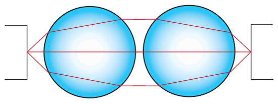
To couple light from one fiber optic to another fiber optic of similar $ \small{\text{NA}} $, two identical ball lenses can be used. Place the two ball lenses at the back focal length from the fibers as shown in Figure 4. If the optical fibers have the same $ \small{\text{NA}} $, then the same logic as in Example 1 can be applied.


or view regional numbers
QUOTE TOOL
enter stock numbers to begin
Copyright 2023 | Edmund Optics, Ltd Unit 1, Opus Avenue, Nether Poppleton, York, YO26 6BL, UK
California Consumer Privacy Acts (CCPA): Do Not Sell or Share My Personal Information
California Transparency in Supply Chains Act
The FUTURE Depends On Optics®