


What are Beamsplitters?

Beamsplitter Construction | Types of Beamsplitters
Beamsplitters are optical components used to split incident light at a designated ratio into two separate beams. Additionally, beamsplitters can be used in reverse to combine two different beams into a single one. Beamsplitters are often classified according to their construction: cube or plate (Table 1).
| Table 1: Comparison of Cube and Plate Beamsplitters | |
|---|---|
| Cube Beamsplitters | Plate Beamsplitters |

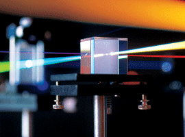
Figure 1: Cube Beamsplitter |

Figure 2: Plate Beamsplitter |
|
Cube beamsplitters are constructed using two typically right angle prisms (Figure 1). The hypotenuse surface of one prism is coated, and the two prisms are cemented together so that they form a cubic shape. To avoid damaging the cement, it is recommended that the light be transmitted into the coated prism, which often features a reference mark on the ground surface. |
Plate beamsplitters consist of a thin, flat glass plate that has been coated on the first surface of the substrate (Figure 2). Most plate beamsplitters feature an anti-reflection coating on the second surface to remove unwanted Fresnel reflections. Plate beamsplitters are often designed for a 45° AOI. For substrates with a 1.5 index of refraction and a 45° AOI, beam shift distance (d) can be approximated using the equation in Figure 2. |
Types of Beamsplitters
Standard Beamsplitters are commonly used with unpolarized light sources, such as natural or polychromatic, in applications where polarization state is not important. They are designed to split unpolarized light at a specific Reflection/Transmission (R/T) ratio with unspecified polarization tendencies.
Polarizing beamsplitters are designed to split light into reflected S-polarized and transmitted P-polarized beams. They can be used to split unpolarized light at a 50/50 ratio, or for polarization separation applications such as optical isolation (Figure 3).

Figure 3: Polarizing Beamsplitter
Non-polarizing beamsplitters split light into a specific R/T ratio while maintaining the incident light’s original polarization state. For example, in the case of a 50/50 non-polarizing beamsplitter, the transmitted P and S polarization states and the reflected P and S polarization states are split at the design ratio. These beamsplitters are ideal for maintaining polarization in applications utilizing polarized light (Figure 4).

Figure 4: Non-Polarizing Beamsplitter
Dichroic Beamsplitters split light by wavelength. Options range from laser beam combiners designed for specific laser wavelengths to broadband hot and cold mirrors for splitting visible and infrared light. This type of beamsplitter is commonly used in fluorescence applications.
Beamsplitter Extinction Ratio
In addition to an R/T ratio, some beamsplitters may also have a specified extinction ratio. This is defined as the ratio of transmitted p-polarized light to s-polarized light, or Tp/Ts. However, it is important to recognize that Tp/Ts is not usually equal to the ratio of reflected s-polarized light to p-polarized light, or Rs/Rp.
Beamsplitters are generally effective at reflecting s-polarization but they are not as effective at preventing p-polarization from reflecting. This occurs because when s-polarized light hits the reflecting surface, the electric field is in the same plane as the surface. When p-polarized light hits the reflecting surface, the field has components both in the surface plane and normal to the surface. The reflectivity of the two components is not the same, but the reflector has to deal with both at the same time. This makes transmitted light almost free of s-polarization, but reflected light is not free of p-polarization. As a consequence, the ratio of Tp/Ts is almost always better than the ratio of Rs/Rp.


or view regional numbers
QUOTE TOOL
enter stock numbers to begin
Copyright 2023 | Edmund Optics, Ltd Unit 1, Opus Avenue, Nether Poppleton, York, YO26 6BL, UK
California Consumer Privacy Acts (CCPA): Do Not Sell or Share My Personal Information
California Transparency in Supply Chains Act
This content may include material that has been generated or modified using artificial intelligence (AI).
The FUTURE Depends On Optics®