


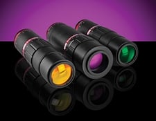
Laser Beam Expanders
This is Sections 6.1, 6.2, 6.3, 6.4, and 6.5 of the Laser Optics Resource Guide.
Laser beam expanders increase the diameter of a collimated input beam to a larger collimated output beam for applications such as laser scanning, interferometry, and remote sensing. Contemporary laser beam expanders are afocal systems developed from well-established optical telescope fundamentals. In such systems, the object rays enter parallel to the optical axis of the internal optics and exit parallel to them. This means that the entire system does not have a focal length.
Telescope Theory
Optical telescopes, traditionally used to view distant objects such as celestial bodies in outer space, are divided into two types: refracting and reflecting. Refracting telescopes utilize lenses to refract, or bend, light, while reflecting telescopes utilize mirrors to reflect light.
There are two categories of refracting telescopes: Keplerian and Galilean. A Keplerian telescope consists of lenses with positive focal lengths separated by the sum of their focal lengths (Figure 1). The lens closest to the object being viewed, or source image, is called the objective lens, while the lens closest to the eye, or image created, is called the image lens.
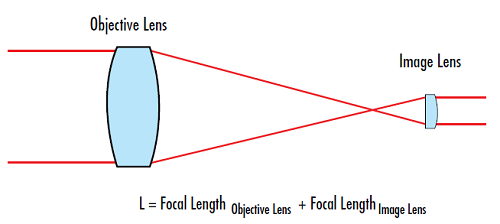
Figure 1: Keplerian telescope
A Galilean telescope consists of a positive lens and a negative lens that are also separated by the sum of their focal lengths (Figure 2). However, since one of the lenses is negative, the separation distance between the two lenses is much shorter than in the Keplerian design. While using the effective focal length of the two lenses will provide a good approximation of the total length, using the back focal length will provide the most accurate length.
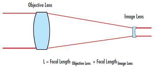
Figure 2: Galilean telescope
The magnifying power, or the inverse of the magnification, of a telescope is based upon the focal lengths of the objective and eye lenses:
If the magnifying power is greater than 1, the telescope magnifies. When the magnifying power is less than 1, the telescope minifies.
Beam Expander Theory
In a laser beam expander, the placement of the objective and image lenses is reversed. Keplerian beam expanders consist of two lenses with positive focal lengths separated by the sum of their focal lengths. They offer high expansion rations and allow for spatial filtering because the collimated input beam focuses to a spot between the objective and image lenses, producing a point within the system where the laser's energy is concentrated (Figure 3). However, this heats the air between the lenses, deflecting light rays from their optical path and potentially leading to wavefront errors especially in high-power laser applications.
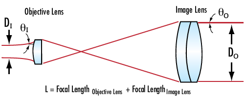
Figure 3: Keplerian beam expanders have an internal focus which is detrimental to high power applications, but useful for spatial filtering in lower power applications
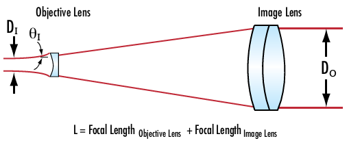
Figure 4: Galilean beam expanders have no internal foci and are ideally suited for high power lasers applications
When using the Keplerian or Galilean designs in laser beam expander applications, it is important to be able to calculate the output beam divergence. This determines the deviation from a perfectly collimated source. The beam divergence is dependent on the diameters of the input and output laser beams.
The magnifying power (MP) can now be expressed in terms of the beam divergences or beam diameters.
When interpreting Equation 4 and Equation 5, one can see that while the output beam diameter (D0) increases, the output beam divergence (θO) decreases and vice versa. Therefore, when using a beam expander to minimize the beam, its diameter will decrease but the divergence of the laser will increase. The price to pay for a small beam is a large divergence angle.
In addition, it is important to be able to calculate the output beam diameter at a specific working distance (L). The output beam diameter is a function of the input beam diameter and the beam divergence after a specific working distance (L) (Figure 5).
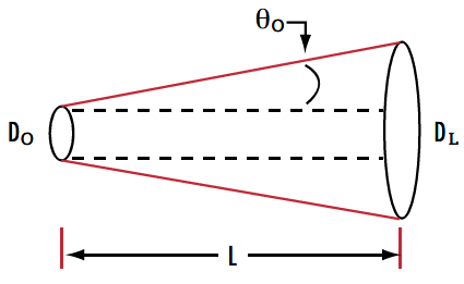
Figure 5: A laser's input beam diameter and divergence can be used to calculate the output beam diameter at a specific working distance
Laser beam divergence is specified in terms of a half angle, which is why a factor of 2 is required in the second term in Equation 6.
A beam expander will increase the input beam and decrease the input divergence by the Magnifying Power. Substituting Equations 4 and 5 with Equation 6 results in the following:
Application 1: Reducing Power Density
Beam expanders increase the beam area quadratically with respect to their magnification without significantly affecting the total energy contained within the beam. This results in a reduction of the beam’s power density and irradiance, which increases the lifetime of laser components, reduces the chances of laser induced damage, and enables the use of more economical coatings and optics.
Application 2: Minimizing Beam Diameter at a Distance
Although it may seem unintuitive, increasing the diameter of a laser using a beam expander may result in a smaller beam diameter far from the laser aperture. A beam expander will increase the input laser beam by a specific expansion power while decreasing the divergence by the same expansion power, resulting in a smaller collimated beam at a large distance. Laser beam expanders can also be used in reverse to reduce beam diameter rather than expanding it. This will invert the magnifying power, but divergence will be increased.
Example
A numerical example to explore the previously mentioned beam expander equations:
Initial Parameters
Beam expander magnifying power = MP = 10X
Input beam diameter = 1mm
Input beam divergence = 0.5mrad
Working distance = L = 100m
Calculated Parameter
Beam diameter at distance L:
Compare this to the beam diameter without using a beam expander by using Equation 6.
Using a 10X beam expander reduced the output beam diameter 100m away by over a factor of 5 when compared to the same laser without a beam expander.
Application 3: Minimizing Focused Spot Size
Spot size is typically defined as the radial distance from the center point of maximum irradiance to the point where the intensity drops to 1/e2 of the initial value (Figure 6). The focused spot size of an ideal lens can be calculated by using wavelength (λ), the focal length of the lens (f), the input beam diameter (DI), the refractive index of the lens (n), and the beam’s M2 factor, which represents the degree of variation from an ideal Gaussian beam.
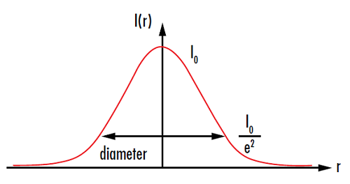
Figure 6: Spot size is usually measured at the point where the intensity I(r) drops to 1/e2 of the initial value I0
Spot size is fundamentally determined by the combination of diffraction and aberrations illustrated by red and blue, respectively, in Figure 7. Generally, when focusing laser beams, spherical aberration is assumed to be the only and dominant type of aberration, which is why Equation 11 only takes spherical aberration into account. In regards to diffraction, the shorter the focal length, the smaller the spot size. More importantly, the larger the input beam diameter the smaller the spot size.
By expanding the beam within the system, the input diameter is increased by a factor of MP, reducing the divergence by a factor of MP. When the beam is focused down to a small spot, the spot is a factor of MP smaller than that of an unexpanded beam for an ideal, diffraction-limited spot. However, there is a tradeoff with spherical aberration because it increases along with the input beam diameter.
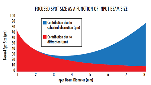
Figure 7: At small input beam diameters, the focused spot size is diffraction limited. As the input beam diameter increases, spherical aberration starts to dominate the spot size
Application 4: Compensating for Input Laser Beam Variability
Most commercial lasers specify an output beam diameter of the laser at the aperture with a tolerance that is often on the order of 10% or more. For many laser applications, a specific beam diameter is required at the end of the system. A variable beam expander can be inserted into the system to compensate for variability between individual laser units, ensuring that the final beam diameter is consistent for all systems.
Beam Expander Selection Criteria
When choosing a beam expander for an application, certain criteria must be determined in order to achieve the correct performance.
Sliding vs. Rotating Divergence Adjustment:
The mechanics used to focus a beam expander or change the magnification of a variable beam expander are typically classified into two different types: sliding and rotating. Rotating divergence adjustment, such as threaded focusing tubes, rotate the optical elements during translation. They have a lower cost than sliding divergence adjustment due to their simplified mechanics, but they create the potential for beam wander due to the element rotation (Figure 8).
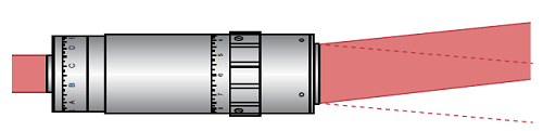
Figure 8: Exaggerated illustration of the beam wander that may be caused by rotating focus mechanisms
Sliding divergence adjustment, such as helicoid barrels, translate the internal optics without rotating them, thus minimizing beam wander. However, this requires more complex mechanics than those of rotating focus mechanisms, increasing system cost. Poorly designed sliding optics may also have too much freedom of movement in the mechanics. While the pointing error in these poorly designed designs will not rotate when adjusted, it will be larger than for rotating optics or correctly designed sliding optics.
Internal Focus:
Keplerian beam expanders contain an internal focus that may be problematic in high power systems. The intense focused spot can ionize the air or lead to wavefront errors as a result of the heat deflecting light rays. Because of this, most beam expanders are Galilean to avoid complications caused by internal focusing. However, certain applications require spatial filtering which is only possible in Keplerian designs because of the internal focus capability.
Reflective vs. Transmissive:
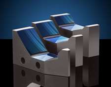
Reflective beam expanders utilize curved mirrors instead of transmissive lenses to expand a beam (Figure 9). Reflective beam expanders are much less common than transmissive beam expanders, but have several advantages that make them the right choice for certain applications. Reflective beam expanders do not suffer from chromatic aberration, whereas the magnification and output beam collimation of transmissive beam expanders is wavelength dependent. While this is not relevant for many laser applications because lasers tend to lase at a single wavelength, it may be critical in broadband applications. The achromatic performance of reflective beam expanders is required for multi-laser systems, some tunable lasers, and ultrafast lasers. Ultrafast lasers inherently span a broader wavelength range than other lasers due to their extremely short pulse duration. Quantum cascade lasers also benefit from reflective beam expanders as transmissive options may not exist at their operating wavelengths.
Figure 9: Unlike transmissive beam expanders, the curved mirrors of this Canopus Reflective Beam Expander expand the incident laser beam. The holes on the side of the beam expander are integrated mounting features
Beam Expander Selection Guide
View NowEdmund Optics Products
The TECHSPEC® Scorpii Nd:YAG Beam Expanders are available for applications where cost is the driving factor. Featuring 2-element Galilean designs with diffraction limited performance at YAG wavelengths, the Scorpii Nd:YAG Beam Expanders offer a variety of magnification ranges from 2X to 10X ideal for prototyping and OEM integration.
The TECHSPEC® Vega Laser Line Beam Expanders provide excellent value with λ/10 performance at design wavelength for apertures up to 4 mm. Featuring laser line V-coats for Nd:YAG harmonics down to 266 nm, these Galilean Designs use Fused Silica elements and provide divergence adjustability.
Examples of the application of the Galilean telescope design to laser beam expanders can be found in several Edmund Optics products, all of which can be used to collimate and focus laser beams. Our TECHSPEC® Arcturus HeNe Beam Expanders is a simple two-lens design, consisting of a negative lens and achromatic lens. Drawing of the internal optical elements is shown for reference.
Our TECHSPEC® Vega Broadband Beam Expanders feature broadband, divergence adjustable designs ideal for demanding tunable laser sources. They are optimized at a wide range of wavelengths and feature λ/10 transmitted wavefront error and no internally focusing ghost images, making them compatible with high power laser sources.
Our TECHSPEC® Draconis Broadband Beam Expanders improves upon the simple two-lens design with a proprietary multi-element lens design that enhances its ability to create a collimated or focused laser beam diameter at a long working distance.
The patent pending TECHSPEC® Canopus Reflective Beam Expanders are easily mounted due to a variety of integrated alignment features. They feature broadband performance with minimal wavefront distortion from the UV to Infrared from 250nm to 10μm. Their monolithic structure provides performance stability independent of changes in temperature.
Our TECHSPEC® Research-Grade Variable Beam Expanders can continuously adjust magnification and divergence while keeping a constant overall housing length. They are ideal for prototyping, R&D, and other applications requiring magnification adjustment.
References
- Greivenkamp, John E. Field Guide to Geometrical Optics. Vol. FG01. Bellingham, WA: SPIE—The International Society for Optical Engineers, 2004.
- Smith, Warren J. Modern Optical Engineering. 3rd ed. New York, NY: McGraw-Hill Education, 2000.


or view regional numbers
QUOTE TOOL
enter stock numbers to begin
Copyright 2023 | Edmund Optics, Ltd Unit 1, Opus Avenue, Nether Poppleton, York, YO26 6BL, UK
California Consumer Privacy Acts (CCPA): Do Not Sell or Share My Personal Information
California Transparency in Supply Chains Act
This content may include material that has been generated or modified using artificial intelligence (AI).
The FUTURE Depends On Optics®