Engineers are available to assist.

|
|
New tabletop sources make applications from 10-100nm more accessible |
|
|
EUV applications include metrology, nanoscale imaging, and electron spectroscopy |
|
|
EUV systems often use reflective optics as high absorption makes refraction impractical |
|
|
Surface roughness is critical because scatter is much higher at shorter wavelengths |
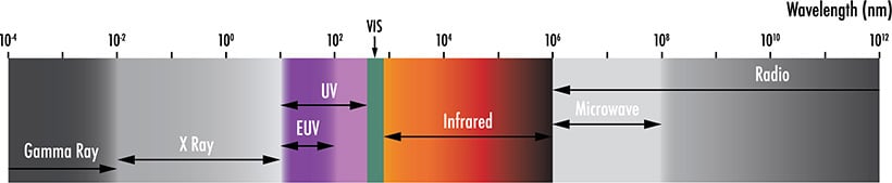
Extreme ultraviolet (EUV) radiation encompasses the band of wavelengths from roughly 10nm to 100nm, between the X-ray and deep UV (DUV) spectral regions. With numerous pressing applications in the EUV region including lithography, nanoscale imaging, and spectroscopy, much effort has recently been focused on developing compact EUV sources. That effort has led to the commercial availability of several types of EUV light sources.
EUV radiation is absorbed strongly in nearly all materials, so optical components are almost always reflective, not transmissive. Because the wavelength is short, EUV optics have surface quality requirements that are more demanding than those for visible-light components. While producing EUV optics is not easy due to their demanding requirements, it is worth the effort because of the benefits of utilizing EUV radiation for high resolution imaging, spectroscopy, and materials processing.
The first practical EUV radiation sources were huge devices available only to large research labs and lithography companies, but recent advancements in EUV technology has made way for much smaller and more accessible tabletop EUV systems. High Harmonic Generation (HHG) systems and capillary discharge lasers are two of the more promising new EUV tabletop sources, producing beams of coherent radiation with low divergence.
New compact EUV sources are spawning a multitude of emerging EUV applications including high resolution imaging, electron spectroscopy, molecular and solid state dynamics research, and nano-machining.
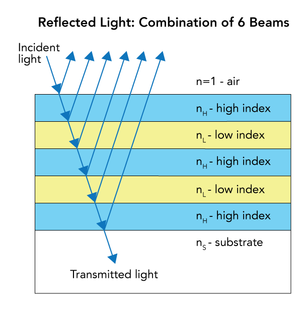
EUV systems need to be contained in a vacuum because wavelengths below 100nm cannot be transmitted through air. Similarly, EUV radiation has extremely high absorption in almost all materials, so optical components in EUV applications are nearly always reflective. Scatter is higher at short wavelengths, which makes surface roughness, surface flatness, and other surface tolerances important for EUV optics. A common type of mirror used in EUV applications is the multilayer Bragg mirror, where a periodic stack of two different materials causes a specific band of wavelengths to constructively interfere and reflect. Part of the incident beam is reflected at each interface in the stack. EUV multilayer mirrors have a very narrow bandwidth, on the order of 1nm, requiring EUV optics of this type to be specifically matched to the wavelength of the source.
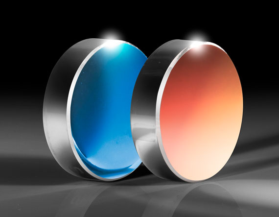 Extreme Ultraviolet (EUV) Flat Mirrors
Extreme Ultraviolet (EUV) Flat Mirrors are multilayer Bragg reflectors with reflective coatings deposited on a super-polished single crystal silicon substrate resulting in a surface roughness less than 3Å. They are designed for maximum achievable reflectance at their design wavelength and angle of incidence. The mirrors are available with either a 5° or 45° angle of incidence (AOI).
Learn More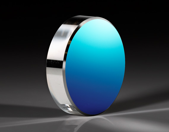 Extreme Ultraviolet (EUV) Spherical Mirrors
Extreme Ultraviolet (EUV) Spherical Mirrors feature multilayer Mo/Si coatings just like the Extreme Ultraviolet (EUV) Flat Mirrors, but they utilize a curved substrate for focusing unpolarized EUV sources at a 5° angle of incidence. They offer >60% reflection at 13.5nm, a <3Å RMS surface roughness, and narrow pass band of 0.5nm.
Learn More Why are the Extreme Ultraviolet (EUV) Flat Mirrors designed for 13.5nm?
Why do the Extreme Ultraviolet (EUV) Flat Mirrors use single crystal silicon substrates and not fused silica?
Why are the Extreme Ultraviolet (EUV) Flat Mirrors designed for 13.5nm?
Why do the Extreme Ultraviolet (EUV) Flat Mirrors use single crystal silicon substrates and not fused silica?
While some EUV optics use fused silica substrates, EO offers Extreme Ultraviolet (EUV) Flat Mirrors with single crystal silicon substrates due to their superior thermal stability compared to fused silica.
Why can’t transmissive optics be used with EUV radiation?
EUV photons have an energy of around 90eV; the typical ionization energies of organic materials and metals are 7-9eV and 4-5eV respectively. Consequently, EUV photons are easily absorbed, generating photoelectrons and secondary electrons which prevents EUV radiation from transmitting through virtually all materials.
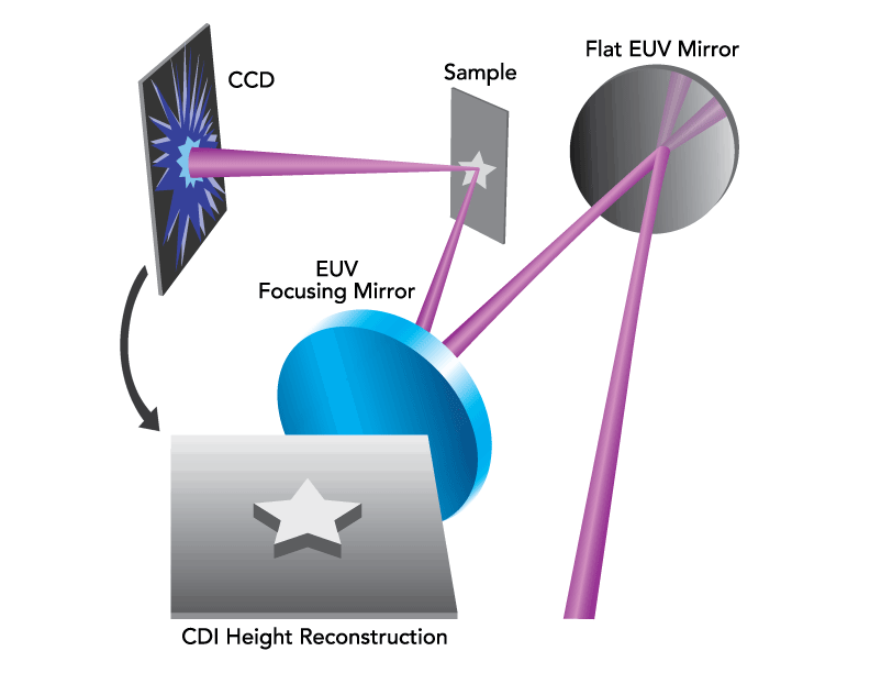
How are images produced in coherence diffraction imaging (CDI) if the light scattering off of the sample is not focused back down into an image on the CCD detector?
The radiation scattering off of the object creates a reciprocal space diffraction pattern on the detector. An inverse Fourier transform algorithm is applied to the recorded pattern to reconstruct an image. Instead of using a lens system to form an image on a detector, software is used to convert the scattered diffraction pattern into a height map of the object.


or view regional numbers
QUOTE TOOL
enter stock numbers to begin
Copyright 2023 | Edmund Optics, Ltd Unit 1, Opus Avenue, Nether Poppleton, York, YO26 6BL, UK
California Consumer Privacy Act (CCPA): Do Not Sell or Share My Personal Information
California Transparency in Supply Chains Act