


Precision Tolerances for Spherical Lenses
Edmund Optics® has improved a variety of the standard tolerances for our TECHSPEC® spherical lenses. These improvements were specifically designed to facilitate "drop in" assemblies, reducing the need for complicated assembly procedures such as active alignment. These changes improve performance and make it easier to integrate our lenses into OEM applications. The precision specification updates were made through process improvements at our world class spherical manufacturing facilities in Japan, Singapore, and the USA, where EO produces millions of lenses each year. The improved specifications implemented include:
Diameter Tolerance: All of our TECHSPEC® spherical lenses, regardless of size, are now held to a diameter tolerance of +0.000/-0.025mm. Maintaining the diameter within 25µm ensures the lenses will seat and align accurately within a well-designed barrel, aligning the optical axis of the lens with the mechanical axis of the assembly.
Diameter tolerance is a critical mechanical tolerance that must be considered when mounting an optic. Deviations from the nominal diameter may prevent lenses from seating properly in their mounting fixture, leading to decenter or tilt within the optical assembly. The image below shows a lens that is not securely held inside of a barrel due to diameter error:
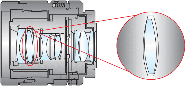
Figure 1: Effects of Diameter Error
Centration: All of our TECHSPEC® singlet lenses with a focal length >10mm now feature a centration of <1 arcminute. This precision alignment of the optical axis ensures the lenses can be used in demanding imaging applications. When combined with the precision diameter tolerances mentioned above, this reduced wedge specification implements minimal image runout in an optical assembly. The image below shows an image runout caused by centration errors:
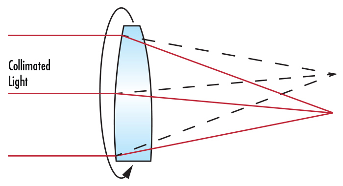
Figure 2: Effects of Centration Errors
Surface Quality: All of our TECHSPEC® spherical lenses, regardless of size, are now held to a scratch-dig value of 40-20. This precision cosmetic specification ensures the lenses can be used in demanding laser-based systems. Even minor scratches or pits on the optical surface can lead to scattered light, which can be detrimental in laser-enabled applications.
Surface quality also impacts the laser damage threshold of a lens. Lenses with poor surface quality may fail when subject to moderate laser power or fluence. Scratches and digs in a lens could also cause laser light to scatter back and forth, destroying the coating. The image below displays an instance where a coating was destroyed by laser light:
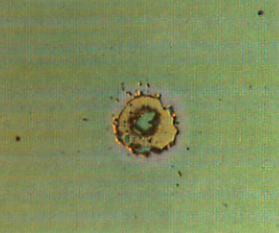
Figure 3: Coating Destroyed from a 73.3 J/cm2 Laser
Edmund Optics’ standard surface quality of 40-20, along with our durable AR coatings, enables our standard TECHSPEC® lenses to be used with lasers with up to approximately 7J/cm2, depending on the wavelength. View our Anti-Reflection (AR) Coatings application note for a full list of recommended energy limits for our standard Broadband Anti-Reflection Coatings.
| Spherical Lens Manufacturing Specifications | |||
| Commercial | Precision | High Precision | |
| Diameter | 4 – 200mm | 4 – 200mm | 4 – 200mm |
| Diameter Tolerance | +0/-0.100mm | +0/-0.025mm | +0/-0.010mm |
| Thickness | ±0.100mm | ±0.050mm | ±0.010mm |
| Surface Sag | ±0.050mm | ±0.025mm | ±0.010mm |
| Clear Aperture | 80% | 90% | 90% |
| Radius | ±0.3% | ±0.1% | Fix to Test Plate |
| Power (P - V) | 3.0λ | 1.5λ | λ/2 |
| Irregularity (P - V) | 1.0λ | λ/4 | λ/20 |
| Centering (Beam Deviation) | 3 arcmin | 1 arcmin | 0.5 arcmin |
| Bevel (Face width @45 degrees) | <1.0mm | <0.5mm | <0.25mm |
| Surface Quality | 80-50 | 40-20 | 10-5 |
Application Examples
Imaging Lens
Our lenses are ideal for use in demanding imaging applications due to the precision alignment of the optical axis. For example, the image below shows how a tightened centration tolerance allows an imaging lens to achieve much better resolution. In this case, with <1 arcminute decenter, the imaging lens can achieve a resolution of around 128 lp/mm at 20% contrast. However, when 2 of the elements were relaxed to allow <6 arcminute decenter, the imaging lens could only achieve a resolution of around 86 lp/mm at 20% contrast.
Rather than relying on complex and costly alignment procedures to produce acceptable performance of the imaging assembly, we were able to increase the resolution by approximately 50% by simply requiring tighter tolerances on the diameter and centration of the individual lens elements. Reducing the need for complicated assembly procedures, such as active alignment, saves time and expense for any application or assembly.
Figure 4: Effects of Centration Errors on Resolution (Top) All elements < 1 arcmin decenter (Bottom) Two elements < 6 arcmin decenter
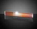
Beam Expander
In beam expanders, centration errors could result in beam wander, producing an output beam that is not parallel to the input beam. Beam wander complicates the alignment of laser systems by requiring the mechanical housing to be tilted in order to compensate for the misalignment of the input and output axes. This beam wander is shown in the image below:
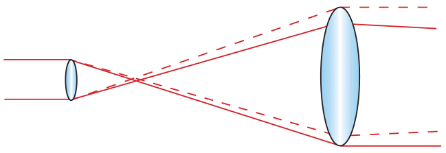
Figure 5: Effects of Centration Errors on a Beam Expander
If system mechanics do not allow for an angular adjustment of the collimator, energy loss may occur due to the tilted beam getting clipped as it propagates through the system. Tightly controlling the diameter and centration of the lens elements within the laser beam expander eliminates the need for expensive mechanical solutions to beam wander, simplifying the laser system and reducing the overall cost.


or view regional numbers
QUOTE TOOL
enter stock numbers to begin
Copyright 2023 | Edmund Optics, Ltd Unit 1, Opus Avenue, Nether Poppleton, York, YO26 6BL, UK
California Consumer Privacy Act (CCPA): Do Not Sell or Share My Personal Information
California Transparency in Supply Chains Act