


Optical Prism Application Examples
The angle, position, and number of surfaces of a prism help define the type and function. To understand how the most popular prisms work and how each can best be used in light reflection and refraction applications, consider right angle prisms, roof prisms, and combination prisms. For the theory of how prisms work and a selection guide with over ten unique geometries, view Introduction to Optical Prisms.
Right Angle Prism
By far the most commonly used prism is the 45° - 90° - 45° prism, known popularly as the right angle prism. It can be used in many ways to achieve different results pertaining to image parity or deviation and is named so for the angles on its triangular faces. The most common application of the 45° - 90° - 45° prism is to treat it as a right angle prism, which has only a single reflection that deviates the incident ray by 90°. The produced image will then become left-handed, but depending upon the position of the prism, can be inverted or reverted (Figure 1).
Figure 1: 45° - 90° - 45° as a Right Angle Prism Showing Inversion (Left) and Reversion (Right)
Using the hypotenuse face of the prism rather than the leg faces allows for another configuration known as the porro prism. This produces a right-handed image since two reflections occur. The ray's direction is reversed when using a porro prism since the object enters and the image exits the same face. The position of the prism determines whether a rotation or just a deviation occurs (Figure 2).

Figure 2: Fixed 180° Rotation with a Porro System
Lastly, a 45° - 90° - 45° prism can also be used as a dove prism. A dove prism rotates the image 180°, but since only one reflection occurs, it will become either reverted or inverted depending on the position of the prism (Figure 3).

Figure 3: 180° Rotation with a Right Angle Prism, Similar to a Dove Prism
Roof Prism
A prism roof consists of two reflecting surfaces located 90° from each other. It is equivalent in function when compared to any other reflecting surface, except handedness does not change. A good example of this is the amici (roof) prism, which is basically a right angle prism with a roof. Under this configuration, a deviation of 90° still occurs, but without changing parity. A roof prism is often used in conjunction with other prisms in order to achieve the desired parity.
Combination Prisms
Many combination prisms are possible with slight adjustments to the orientation and/or coating applied to the surfaces of the individual prisms used. Ultimately, the application dictates the type of combination necessary. Consider the most well-known combination prisms: porro system, Pechan (roof) prism, and beamsplitters.
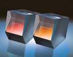
A porro prism is often used in combination with itself to create a porro system (Figure 4) with a total of four reflections. Due to its ability to produce an upside down image rotated 180° from the original while maintaining right-handedness, this type of image erection prism is extremely useful for binocular and telescope applications. It is important to keep in mind that the ray path does become displaced, a fact that must be taken into account when adjusting the rest of the optical components used with a porro system, such as an objective lens and eyepiece for binoculars.

Figure 4: Fixed 180° Rotation with a Porro System
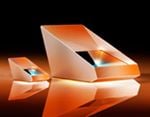
Another type of image erection prism is the Pechan (roof) prism (Figure 5) comprised of a Schmidt prism and a half-penta prism. It carries six total reflections and a small air gap to allow for TIR inside the prism system. The even number of reflections enables the image to stay right-handed. No displacement is produced along the object's axis if aligned precisely, though the image is inverted.

Figure 5: 180° Rotation with a Pechan-Roof Prism
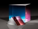
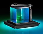
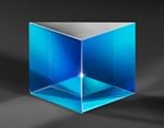
Lastly, but possibly the most recognizable combination prism, is a cube beamsplitter (Figure 6). Unlike a plate beamspitter (often a plano-window with dielectric and anti-reflection (AR) coatings), a cube beamsplitter is comprised of two right angle prisms. Typically, the two prisms are adhered together, but optical contacted beamsplitters exist as well. In order to "split" the incident beam, a dielectric coating is applied to the hypotenuse of one of the right angle prisms. This coating reflects a portion of the beam in one direction, and allows the other to be transmitted through the entire cube. The type of coating determines whether this split is 50/50, 30/70, or 70/30, as well as the specific wavelengths and/or polarizations that are transmitted or reflected. As a result of the precise alignment required by a skilled optician to adhere or contact the two hypotenuses together, it is better to purchase a complete beamsplitter assembly rather than try to use two identical right angle prisms.

Figure 6: Cube Beamsplitter
Edmund Optics manufactures prisms in a range of geometries for simple dispersion to complex, multi optical element applications. Understanding the optical theories behind each specific geometry helps one select the best prism or combination of prisms for any application.


or view regional numbers
QUOTE TOOL
enter stock numbers to begin
Copyright 2023 | Edmund Optics, Ltd Unit 1, Opus Avenue, Nether Poppleton, York, YO26 6BL, UK
California Consumer Privacy Act (CCPA): Do Not Sell or Share My Personal Information
California Transparency in Supply Chains Act