


Best Practices for Better Imaging
Authors: Gregory Hollows, Nicholas James
This is part of the Imaging Resource Guide.
Whether your application is in machine vision, life sciences, security, or traffic solutions, understanding the fundamentals of imaging technology significantly eases the development and deployment of sophisticated imaging systems. While advancements in sensor and illumination technologies suggest limitless system capabilities, there are physical limitations in the design and manufacture of these technologies. Optical components are not an exception to such limitations and optics can often be the limiting factor of system performance. The content provided in this guide is designed to help specify an imaging system, maximize system’s performance, and minimize cost.
Compiled are several simple best practices for creating sophisticated, cost-effective imaging systems useful to most applications. While the list is nearly exhaustive and should be used when designing any imaging system, each application is unique and may require extra consideration.

#1: Allow ample room for the imaging system.
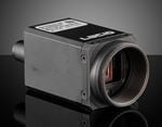
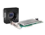
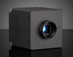
Understanding a system’s space requirements before building is especially crucial for high-resolution and high-magnification requirements. Recent advancements in camera technology have yielded exceptional consumer cameras in small sizes. However, these advancements do little to benefit even intermediate-level industrial imaging systems—partially because of size limitations. Many applications can require complex light geometries, large diameter-long length lenses, and large cameras, in addition to cabling and power sources required to operate equipment. Avoid sacrificing performance by considering spatial feasibility during project planning. Specify the requirements of a project’s vision system first. It is typically easier to arrange electronics and mechanics around the optical portion than otherwise. It is important to note that the illumination scheme is part of the vision system and that the object under inspection may require the use of large or numerous light sources, such as a diffuse dome (see Best Practice #4).
#2: Don’t believe your eyes.
The human eye and brain work together to form an extremely advanced imaging and analysis system capable of filling in information not necessarily present. Additionally, the way in which humans see and process contrast is fundamentally different than imaging systems. Software analysis must be used to ensure image quality and performance requirements are met. Images that look good to a human may not actually be sufficient.
#3: Don’t get too close.
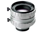
Due to the constraints of physics, attempting to image fields of view (FOV) too large, relative to a lens’s working distance (WD), places excessive demands on the design of the optical components, decreasing system performance and increasing the need for imaging processing and the time in which processing is done. It is recommended that a lens be chosen such that the WD is roughly two to four times as long as the desired FOV width to maximize performance while minimizing cost and complexity. Remember Best Practice #1 and consider the imaging system’s space requirement before building the system.
This practice also applies to the relationship between sensor size and focal length. It is best to have focal length to sensor diagonal ratios of two to four (2:1 to 4:1) to maximize performance.


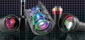
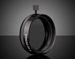
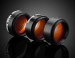
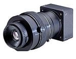
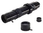
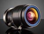
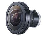
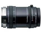
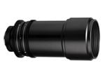
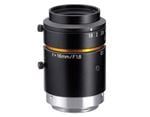
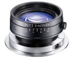
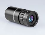
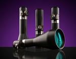
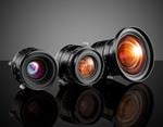
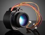
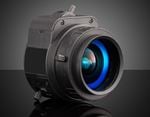
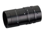
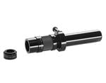
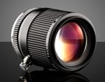
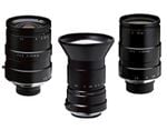
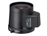
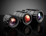
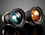
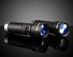
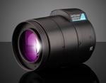
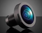
Figure 1: Two lens designs, 1a (left) and 1b (right), with the same FOV and very different WDs.
#4: Illuminate for the occasion.
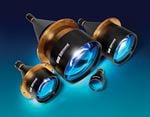
For a lens and sensor to effectively work together, strong contrast must be reproduced by properly lighting the object. The characteristics of the object under inspection and the nature of any defects must be understood so that the proper illumination geometry is used. Remember that these lights can be very large (see Best Practice #1). Learn more about illumination geometries in our Common Illumination Types application note.
#5: Color matters.
The wavelength (color) selected for the illumination can have an enormous impact on system performance. In an application using high-quality optics and a top-of-the-line sensor, switching from broadband to monochromatic illumination, or between specific wavelengths, can significantly improve performance. As with Best Practice #4, the proper choice of wavelength can make the difference between high contrast and no contrast and can be the difference between system success or failure.

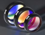
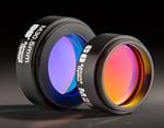
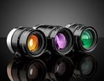
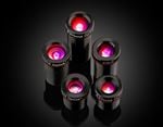
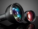
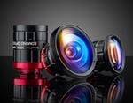
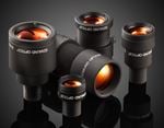
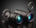
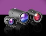
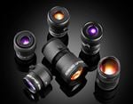
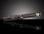
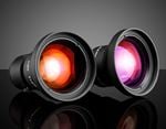
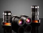
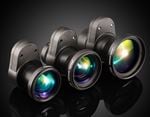
Figure 2: Depending on the wavelength of light, there exists multiple points of the best focus. This image shows three points for three different wavelengths.
Learn how proper filtering techniques can impact system performance in our Types of Filter Technology application note.
#6: High resolution and large depths of field struggle to co-exist.
As shown in Depth of Field and Depth of Focus, maximizing resolution and depth of field (DOF) requires the same variable—the f/#—to move in opposite directions. It is impossible to have a very high resolution over a large DOF. To achieve this may require more elaborate solutions such as using a liquid lens or multiple imaging systems.
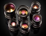
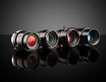
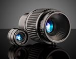
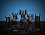
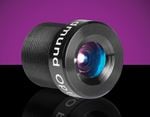
#7: There is no single lens that can do everything.
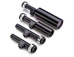
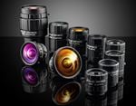
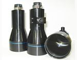
As resolution requirements increase, the ability to decrease aberrations (attributes of optical design that adversely affect performance) becomes increasingly difficult over a wide range of operating parameters. Even without budget constraints, there are physical limitations. For this reason, a wide range of lens solutions for similar applications are required.
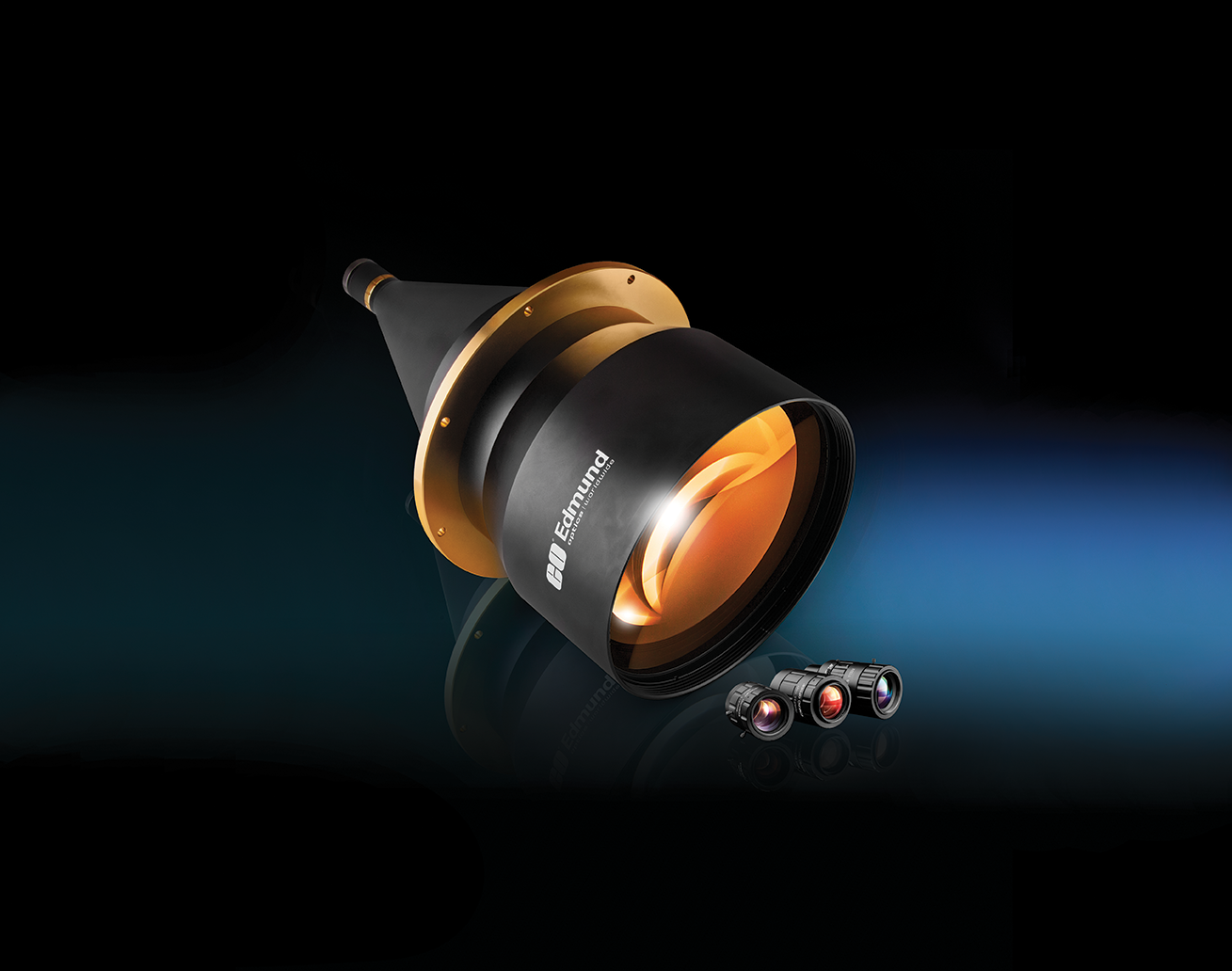
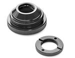
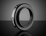
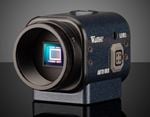
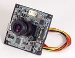
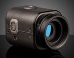
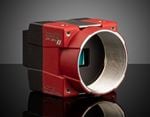
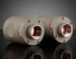
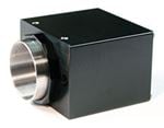
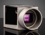
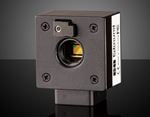
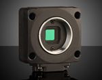
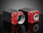
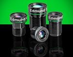
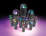
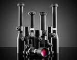
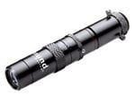
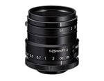
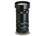
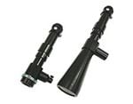
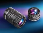
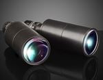
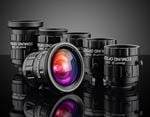
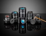
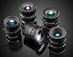
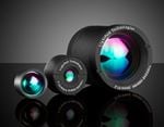
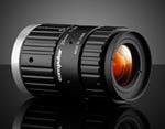
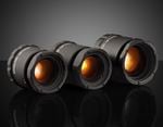
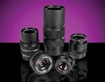
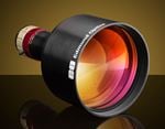
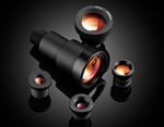
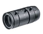
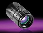
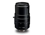
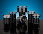
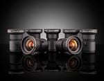
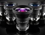
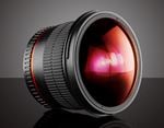
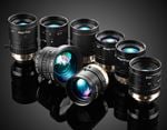
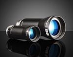
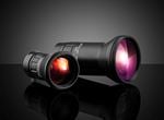
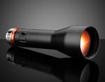
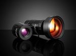
Figure 3: Comparison of two different lens sizes with significantly different applications.
More details on lens performance are found in Types of Machine Vision Lenses.
#8: Thoroughly understand the object to be inspected.
The ability to produce the highest level of contrast on an inspection object is the foundation for imaging. An understanding of the object’s properties, such as its materials or finishes, is critical for success. Additionally, it is not enough to just know what features are considered good or bad. Rather, to guarantee high levels of reliability and repeatability, the range of details to be inspected and the margins for good and bad must be understood.
#9: Be a control freak.
The ability to control the environment into which the imaging system is deployed can significantly affect the reliability and consistency of results. Additionally, it also reduces the likelihood of unintended problems. Whether using filters to increase contrast, baffles to eliminate unwanted light from entering the system, or measurement devices to monitor light sources for spectral stability, controlling the environment will reduce unforeseen difficulties in the future. Some of these techniques are extremely low-cost ways to protect and increase the performance of an expensive imaging system.
#10: Speak up.
Do not be afraid to ask why something will or will not work. Suppliers should be able to explain why components are or are not capable of achieving the desired result. The answer will not always be the same (e.g. the laws of physics or design deficiencies). However, designers and manufacturers must be able to explain the capabilities of their products.
#11: Understand and define the fundamental parameters of the imaging systems.
By narrowing down the specific parameters required for the imaging system, the wide range of available lenses and sensors can be reduced to a manageable selection. Fundamental parameters of an imaging systems are a great place to start and are detailed in the next section.
This is part of the Imaging Resource Guide.


or view regional numbers
QUOTE TOOL
enter stock numbers to begin
Copyright 2023 | Edmund Optics, Ltd Unit 1, Opus Avenue, Nether Poppleton, York, YO26 6BL, UK
California Consumer Privacy Act (CCPA): Do Not Sell or Share My Personal Information
California Transparency in Supply Chains Act