


The Correct Material for Infrared (IR) Applications
Introduction to Infrared | Importance of the Correct Material | Choose the Correct Material | Infrared Comparison
Introduction to Infrared (IR)
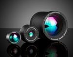
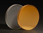
Infrared (IR) radiation is characterized by wavelengths ranging from 0.750 -1000μm (750 - 1000000nm). Due to limitations on detector range, IR radiation is often divided into three smaller regions: 0.750 - 3μm, 3 - 30μm, and 30 - 1000μm – defined as near-infrared (NIR), mid-wave infrared (MWIR), and far-infrared (FIR), respectively (Figure 1). Infrared products are used extensively in a variety of applications ranging from the detection of IR signals in thermal imaging to element identification in IR spectroscopy. As the need for IR applications grows and technology advances, manufacturers have begun to utilize IR materials in the design of plano-optics (i.e. windows, mirrors, polarizers, beamsplitters, prisms), spherical lenses (i.e. plano-concave/convex, double-concave/convex, meniscus), aspheric lenses (parabolic, hyperbolic, hybrid), achromatic lenses, and assemblies (i.e. imaging lenses, laser beam expanders, eyepieces, objectives). These IR materials, or substrates, vary in their physical characteristics. As a result, knowing the benefits of each allows one to select the correct material for any IR application.
Figure 1: Electromagnetic Spectrum
The Importance of Using the Correct Material
Since infrared light is comprised of longer wavelengths than visible light, the two regions behave differently when propagating through the same optical medium. Some materials can be used for either IR or visible applications, most notably fused silica, BK7 and sapphire; however, the performance of an optical system can be optimized by using materials better suited to the task at hand. To understand this concept, consider transmission, index of refraction, dispersion and gradient index. For more in-depth information on specifications and properties, view Optical Glass.
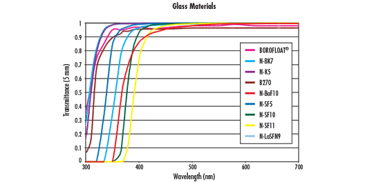
Transmission
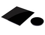
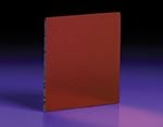
The foremost attribute defining any material is transmission. Transmission is a measure of throughput and is given as a percentage of the incident light. IR materials are usually opaque in the visible while visible materials are usually opaque in the IR; in other words, they exhibit nearly 0% transmission in those wavelength regions. For example, consider silicon, which transmits IR but not visible light (Figure 2).
Figure 2: Uncoated Silicon Transmission Curve
Index of Refraction
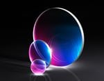
While it is mainly transmission that classifies a material as either an IR or visible material, another important attribute is index of refraction $ \small{ \left( n_d \right) } $. Index of refraction is the ratio of the speed of light in a vacuum to the speed of light within a given material. It is a means of quantifying the effect of light "slowing down" as it enters a high index medium from a low index medium. It is also indicative of how much light is refracted when obliquely encountering a surface, where more light is refracted as $ \small{n_d} $ increases (Figure 3).
Figure 3: Light Refraction from a Low Index to a High Index Medium
The index of refraction ranges from approximately 1.45 - 2 for visible materials and 1.38 - 4 for IR materials. In many cases, index of refraction and density share a positive correlation, meaning IR materials can be heavier than visible materials; however, a higher index of refraction also implies diffraction-limited performance can be achieved with fewer lens elements – reducing overall system weight and cost.
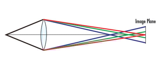
Dispersion
Dispersion is a measure of how much the index of refraction of a material changes with respect to wavelength. It also determines the separation of wavelengths known as chromatic aberration. Quantitatively, dispersion is inversely given by the Abbe number $ \small{ \left( v_d \right) } $, which is a function of the refractive index of a material at the f (486.1nm), d (587.6nm), and c (656.3nm) wavelengths (Equation 1).
Materials with an Abbe number greater than 55 (less dispersive) are considered crown materials and those with an Abbe number less than 50 (more dispersive) are considered flint materials. The Abbe number for visible materials ranges from 20 - 80, while the Abbe number for IR materials ranges from 20 - 1000.
Index Gradient
The index of refraction of a medium varies as the temperature changes. This index gradient $ \left( \tfrac{\text{d} n}{\text{d} T} \right) $ can be problematic when operating in unstable environments, especially if the system is designed to operate for one value of n. Unfortunately, IR materials are typically characterized by larger values of $ \tfrac{\text{d} n}{\text{d} T} $ than visible materials (compare N-BK7, which can be used in the visible, to germanium, which only transmits in the IR in the Key Material Attributes table in Infrared Comparison).
How to Choose the Correct Material
When choosing the correct IR material, there are three simple points to consider. Though the selection process is easier because there is a much smaller practical selection of materials for use in the infrared compared to the visible, these materials also tend to be more expensive due to fabrication and material costs.
- Thermal Properties – Frequently, optical materials are placed in environments where they are subjected to varying temperatures. Additionally, a common concern with IR applications is their tendency to produce a large amount of heat. A material's index gradient and coefficient of thermal expansion (CTE) should be evaluated to ensure the user is met with the desired performance. CTE is the rate at which a material expands or contracts given a change in temperature. For example, germanium has a very high index gradient, possibly degrading optical performance if used in a thermally volatile setting.
- Transmission – Different applications operate within different regions of the IR spectrum. Certain IR substrates perform better depending on the wavelength at hand (Figure 4). For example, if the system is meant to operate in the MWIR, germanium is a better choice than sapphire, which works well in the NIR.
- Index of Refraction – IR materials vary in terms of index of refraction far more than visible materials do, allowing for more variation in system design. Unlike visible materials (such as N-BK7) that work well throughout the entire visible spectrum, IR materials are often limited to a small band within the IR spectrum, especially when anti-reflection coatings are applied.
Figure 4: Infrared Substrate Comparison (Wavelength Range for N-BK7 is Representative for the Majority of Substrates Used for Visible Wavelengths Such as B270, N-SF11, BOROFLOAT®, etc.)
Infrared Comparison
Although dozens of IR materials exist, only a handful is predominantly used within the optics, imaging, and photonics industries to manufacture off-the-shelf components. Calcium fluoride, fused silica, germanium, magnesium fluoride, N-BK7, potassium bromide, sapphire, silicon, sodium chloride, zinc selenide and zinc sulfide each have their own unique attributes that distinguish them from each other, in addition to making them suitable for specific applications. The following tables provide a comparison of some commonly used substrates.
| Key IR Material Attributes | ||||||
|---|---|---|---|---|---|---|
| Name | Index of Refraction, $$ \small{ \left( n_d \right)} $$ | Abbe Number, $$\small{ \left( v_d \right)}$$ | Density | CTE | $$\pmb{\frac{\text{d}\textit{n}}{\text{d}\textit{T}}} $$ |
Knoop Hardness |
| $$ \left[ \tfrac{\text{g}}{\text{cm}^3} \right] $$ | $$ \left[ \times \tfrac{10^{-6}}{^{\text{o}} \text{C}} \right] $$ | $$ \left[ \times \tfrac{10^{-6}}{^{\text{o}} \text{C}} \right] $$ | $$ \left[ \tfrac{\text{kg}_f}{\text{mm}^2}\right] $$ | |||
| Calcium Fluoride (CaF2) | 1.434 | 95.1 | 3.18 | 18.85 | -10.6 | 158.3 |
| Fused Silica (FS) | 1.458 | 67.80 | 2.2 | 0.55 | 11.9 | 500 |
| Germanium (Ge) | 4.003 | N/A | 5.33 | 6.1 | 396 | 780 |
| Magnesium Fluoride (MgF2) | 1.413 | 106.2 | 3.18 | 13.7 | 1.7 | 415 |
| N-BK7 | 1.517 | 64.2 | 2.46 | 7.1 | 2.4 | 610 |
| Potassium Bromide (KBr) | 1.527 | 33.6 | 2.75 | 43 | -40.8 | 7 |
| Sapphire | 1.768 | 72.2 | 3.97 | 5.3 | 13.1 | 2200 |
| Silicon (Si) | 3.422 | N/A | 2.33 | 2.55 | 160 | 1150 |
| Sodium Chloride (NaCl) | 1.491 | 42.9 | 2.17 | 44 | -40.8 | 18.2 |
| Zinc Selenide (ZnSe) | 2.403 | N/A | 5.27 | 7.1 | 61 | 120 |
| Zinc Sulfide (ZnS) | 2.631 | N/A | 5.27 | 7.6 | 38.7 | 120 |
| IR Material Comparison | |
|---|---|
| Name | Properties / Typical Applications |
| Calcium Fluoride (CaF2) | Low Absorption, High Refractive Index Homogeneity |
| Used in Spectroscopy, Semiconductor Processing, Cooled Thermal Imaging | |
| Fused Silica (FS) | Low CTE and Excellent Transmission in IR |
| Used in Interferometry, Laser Instrumentation, Spectroscopy | |
| Germanium (Ge) | High nd, High Knoop Hardness, Excellent MWIR to FIR Transmission |
| Used in Thermal Imaging, Rugged IR Imaging | |
| Magnesium Fluoride (MgF2) | High CTE, Low Index of Refraction, Good Transmission from Visible to MWIR |
| Used in Windows, Lenses, and Polarizers that Do Not Require Anti-Reflection Coatings | |
| N-BK7 | Low-Cost Material, Works Well in Visible and NIR Applications |
| Used in Machine Vision, Microscopy, Industrial Applications | |
| Potassium Bromide (KBr) | Good Resistance to Mechanical Shock, Water Soluble, Broad Transmission Range |
| Used in FTIR spectroscopy | |
| Sapphire | Very Durable and Good Transmission in IR |
| Used in IR Laser Systems, Spectroscopy, and Rugged Environmental Equipment | |
| Silicon (Si) | Low Cost and Lightweight |
| Used in Spectroscopy, MWIR Laser Systems, THz Imaging | |
| Sodium Chloride (NaCl) | Water Soluble, Low Cost, Excellent Transmission from 250nm to 16μm, Sensitive to Thermal Shock |
| Used in FTIR spectroscopy | |
| Zinc Selenide (ZnSe) | Low Absorption, High Resistance to Thermal Shock |
| CO2 Laser Systems and Thermal Imaging | |
| Zinc Sulfide (ZnS) | Excellent Transmission in Both Visible and IR, Harder and More Chemically Resistant than ZnSe |
| Used in Thermal Imaging | |


or view regional numbers
QUOTE TOOL
enter stock numbers to begin
Copyright 2023 | Edmund Optics, Ltd Unit 1, Opus Avenue, Nether Poppleton, York, YO26 6BL, UK
California Consumer Privacy Act (CCPA): Do Not Sell or Share My Personal Information
California Transparency in Supply Chains Act