


Understanding Surface Quality Specifications
This is Sections 9.1 and 9.2 of the Laser Optics Resource Guide.
The surface quality of an optical component is an evaluation of the surface imperfections, such as scratches and pits, or digs, which may be caused during the manufacturing or handling process. Lens Surface quality is more important for laser applications than imaging applications because surface imperfections can be the initiating sites for laser-induced damage. Sensitive systems where maximum signal strength is essential can also suffer from throughput variations and increased scattering from surface imperfections. Optics used with UV wavelengths require tighter surface quality tolerances than optics used with visible or IR systems because shorter wavelengths experience higher amounts of scatter. The specified surface quality directly impacts cost, therefore over-specifying your optics and using a better surface quality than required will unnecessarily increase costs. This makes understanding surface quality specifications and how they impact system performance essential to the success and cost-effectiveness of a system. There are several standards for specifying surface quality such as U.S. Military Performance Specification MIL-PRF-13830B and ISO 10110.
U.S. Standard MIL-PRF-13830B
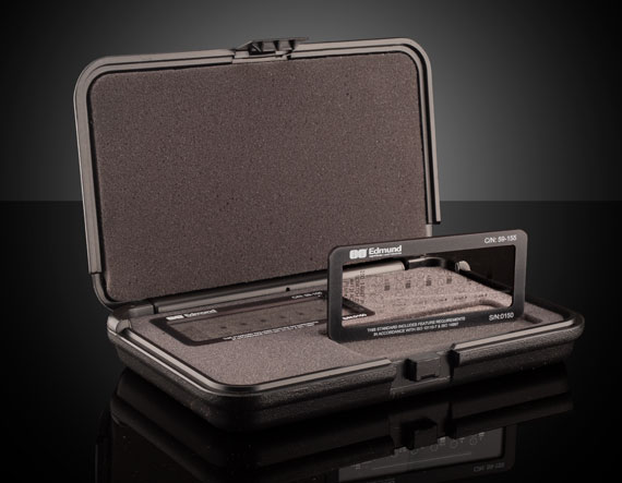
The U.S. Military Performance Specification MIL-PRF-13830B describes surface quality using a “scratch” number followed by a “dig” number based on calibrated standards prescribed therein.1 The scratch number is one of the following arbitrary numbers: 10, 20, 40, 60, or 80, where the brightness of scratches increases from 10 to 80. This number is not an exact measurement, only an indication of the best match of component scratch brightness with calibrated standard scratch brightness. The inspection occurs under specified darkfield illumination conditions, but because it is a subjective visual inspection the results can vary from inspector to inspector (Figure 1).

Figure 1: MIL-PRF-13830B specifies that visual inspection be done using a 40W incandescent or 15W cool white fluorescent lamp
However, the dig number is a measurable quantity: the diameter of the largest component dig, given in 1/100 of millimeters. For example, a component with a 0.4mm diameter dig is represented with a dig number of 40 and one with a 0.2mm diameter with a dig number of 20 (Figure 2).
Figure 2: MIL-PRF-13830B characterizes the surface quality of optics by visually comparing scratches and digs to a calibrated standard
Once all scratches and digs have been quantified, determining the number of allowable defects is required. This number is determined as follows:
Scratches
If a maximum-sized allowable scratch is present on the optic, then the combined length of the maximum sized scratches $ \small{ \left( L_i \right)} $ may not exceed ¼ of the diameter of the optic $ \small{ \left( \phi \right) } $. For non-circular optics, the diameter of the circle with an area equal to that of the optic should be used.
Digs
Digs are pits in the surface of the optic, bubbles, or inclusions. The sum of the dig numbers $ \small{\left( N_i \right)} $ shall not exceed two times the maximum dig specification $ \small{\left( D \right) }$.
There shall be only one maximum sized dig per 20mm of diameter. Thus, if two maximum-sized digs are separated by less than 20mm, the part will not meet the specification. Additionally, all digs with a 10 specification shall be separated by at least 1mm. Digs less than 2.5µm in diameter should be ignored.
A laser optic with a 100mm diameter and specified surface quality of 10-5, based on the above limitations, can have several scratches with a brightness of 10 whose total length is not more than 25mm. It may not have more than 5 maximum-sized digs of 0.05mm (5 Dig Number), and the sum of the diameters of all digs must not exceed 0.5mm.
Scratch-dig specifications of 40-20 are widely considered standard quality for many optical applications. Precision laser applications typically require a scratch-dig of 20-10, whereas the most demanding laser applications, such as intra-cavity laser optics, usually require a scratch-dig of 10-5. Because the impact of surface imperfections on performance is wavelength dependent, UV laser applications often require a surface quality of 10-5, though a 10-5 optic used with a 10.6µm CO2 laser would be overspecified and unnecessarily expensive.
ISO 10110-7 Part 7: Surface Imperfections
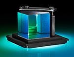
The visual inspection of MIL-PRF-13830B is economical and fast, but its subjective nature lacks precision. ISO 10110-7 is a more quantitative approach for specifying surface quality based on the physical sizes and frequencies of surface defects over a given part area (Figure 3). While this method is more precise than MIL-PRF-13830B, ISO 10110-7 is more time-consuming and therefore more expensive. It is more time-consuming because a microscope with high enough magnification to visualize small surface defects will require a small field of view, so many measurements are required to image a whole sample.
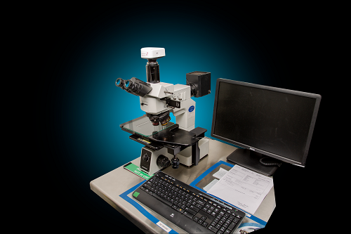
Figure 3: While MIL-PRF-13830B only requires the visual inspection of an optic, ISO 10110-7 requires dimensional analysis using techniques such as differential interference contrast (DIC) microscopy
ISO 10110-7 makes no distinction between scratches and digs and instead treats both simply as surface imperfections.2 Rather than scratch-dig numbers, the 10110-7 indicates the number of allowed imperfections $ \left( \small{N_g} \right) $ and a grade number $ \left( \small{A_g} \right) $ which is equal to the square root of the area of the maximum allowed imperfection (Figure 4).
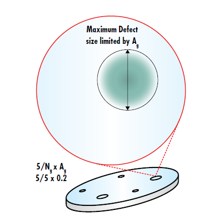
Figure 4: ISO 10110-7 limits the number of allowable defects through $ \left( \small{N_g} \right) $ and limits the maximum size of the imperfections through the grade number A
The ISO surface quality of optical components is expressed on drawings as 5/ $ \small{N_g} $ x $ \small{A_g} $. The total area obscured by imperfections is then given by:
ISO 10110-7 refers to specifying surface quality through $ \small{N_g} $ and $ \small{A_g} $ as the “dimensional” method, but ISO drawings may also indicate surface quality through a “visibility” method identical to MIL-PRF-13830B. 5/60-40 on an ISO print has the same meaning as 60-40 on a print following MIL-PRF-13830B. The benefit of being able to indicate both “dimensional” and “visible” specifications is that it results in prints with all the standardization and lack of notes of an ISO print, with the ability to use the more convenient and cost-effective MIL-PRF-13830B surface quality standard for the majority of applications. The “dimensional” method can then be used for high-precision applications where surface quality is of the highest importance.
Learn About Other Optical Specifications and
Manufacturing Tolerances
Learn About Metrology at Edmund Optics®

References
- U.S. Military Performance Specification. (1997). General specification governing the manufacturing, assembly, and inspection of Optical Components for Fire Control Instruments (Mil-PRF-13830B).
- International Organization for Standardization. (2017). Optics and photonics -- Preparation of drawings for optical elements and systems -- Part 7: Surface imperfections (ISO 10110-7:2017).
More Resources
- Understanding Optical Specifications Application Note
- Cost Impact of Spherical Tolerancing Webinar
- Metrology for Laser Optics Application Note
- Optical Glass Application Note
- EO Preferred Glass Types Application Note
- Subsurface Damage Application Note
- Laser Optics Lab Video Series


or view regional numbers
QUOTE TOOL
enter stock numbers to begin
Copyright 2023 | Edmund Optics, Ltd Unit 1, Opus Avenue, Nether Poppleton, York, YO26 6BL, UK
California Consumer Privacy Act (CCPA): Do Not Sell or Share My Personal Information
California Transparency in Supply Chains Act